Rockwell Automation 20Y PowerFlex 700H, 700S, and 700AFE Drive Fan Systems, Frames 9...14 User Manual
Page 139
Rockwell Automation Publication PFLEX-IN029B-EN-P - August 2014
139
PowerFlex 700H and 700S Drives - Frame 13 Procedures
Chapter 5
8.
Install the voltage feedback circuit board assembly in the reverse order of
removal.
ASIC Circuit Board Assembly Cooling Fan (20-PP01096) Removal and
Installation (Inverter Only)
PowerFlex 700H and 700S drives have an ASIC circuit board located on the V
phase inverter section. It may need to be removed to service the fan inverter
circuit board and cooling fans. Follow these steps to remove the ASIC circuit
board.
1.
Review the General Precautions on page
2.
Remove power from the drive. See Remove Power from the Drive on page
3.
Move the control frame, and remove the screens, airflow plates, and
protective covers from the drive. See Move the Control Frame, and
Remove the Screens, Airflow Plates, and Protective Covers on page
.
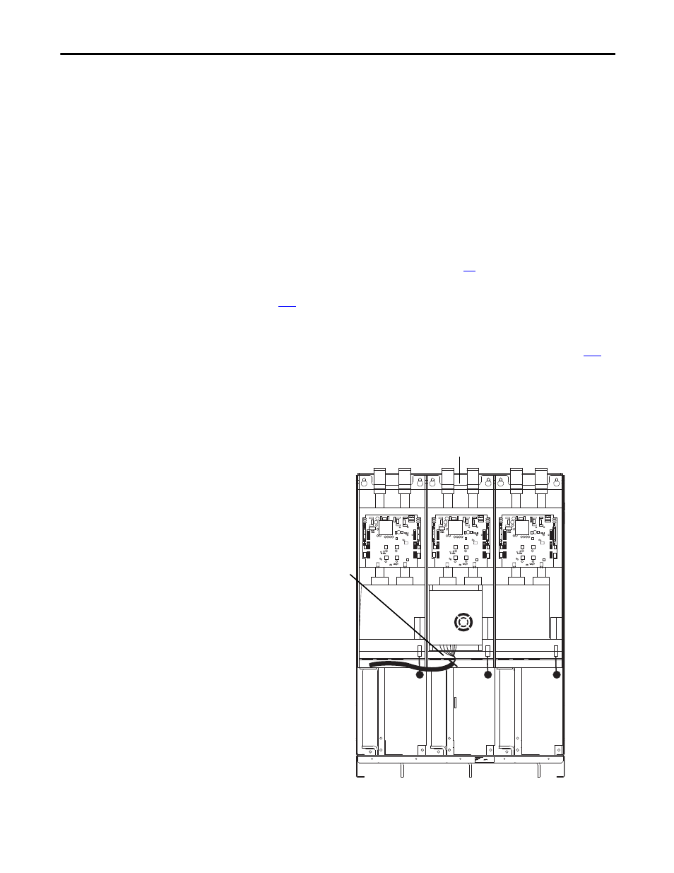
4.
If you are accessing the electrical components within the V phase, cut the
cable tie that secures the ASIC circuit board fiber-optic cable bundle to the
fan housing (if present) and remove the fiber-optic bundle and rubber
grommet from the support bracket in order to allow room for the fan
housing to be removed from the unit.
PowerFlex 700S drive shown
4
V phase power structure