Rockwell Automation 20Y PowerFlex 700H, 700S, and 700AFE Drive Fan Systems, Frames 9...14 User Manual
Page 202
202
Rockwell Automation Publication PFLEX-IN029B-EN-P - August 2014
Chapter 7
PowerFlex 700AFE Drive - Frame 10 Procedures
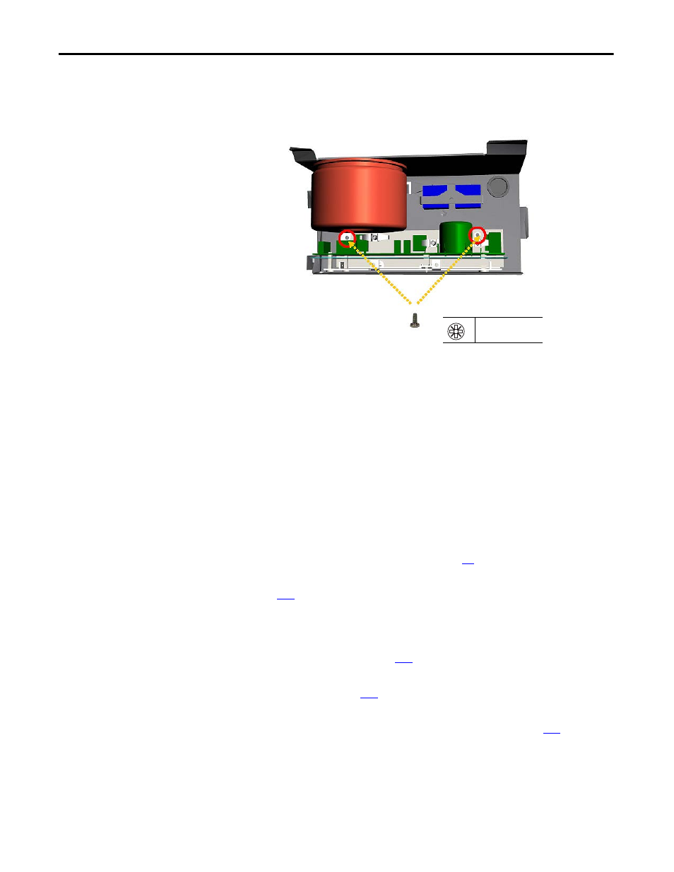
8.
Remove two M4 x 8 mm POZIDRIV screws that secure the fan inverter
board and its heatsink to the assembly carriage and carefully remove the
fan inverter board and its heatsink from the assembly carriage.
9.
Install the main AC fan inverter circuit board in the reverse order of
removal.
Main DC Fan Power Supply Circuit Board (SK-H1-DCFANBD1) Removal and Installation
PowerFlex 700AFE frame 10 drives have a single fan power supply. You can
retrofit an existing AC fan system or replace a DC fan system with a new DC fan
system. See Energy-related Products Fan Efficiency Directive on page 8 for
guidelines on replacing an existing fan system with a new DC fan system.
Follow these steps to remove and replace an existing fan system with a new DC
fan system.
1.
Review the General Precautions on page
2.
Remove power from the AFE. See Remove Power from the AFE on page
3.
If applicable, move the control frame, and remove the screens, airflow
plate, and protective covers from the AFE. See Move the Control Frame,
and Remove the Screens, Airflow Plate, and Protective Covers (IP21 -
Rittal Enclosure) on page
4.
Remove the main fan assembly from the AFE. See Remove the Main Fan
Assembly on page
.
5.
Remove the AC fan inverter assembly from the AFE. See AC Fan Inverter
Assembly (20-FI13301) Removal and Installation on page
.
8
PZ2
3.0 N
•
m (27.0 lb
•
in)
Note: AC fan system shown