Powerflex 700afe – Rockwell Automation 20Y PowerFlex 700H, 700S, and 700AFE Drive Fan Systems, Frames 9...14 User Manual
Page 259
Rockwell Automation Publication PFLEX-IN029B-EN-P - August 2014
259
PowerFlex 700H and 700S Diagnostic Procedures
Appendix A
The fan system topology differs between the ac and dc versions, however, they
contain the similar functions.
PowerFlex 700AFE
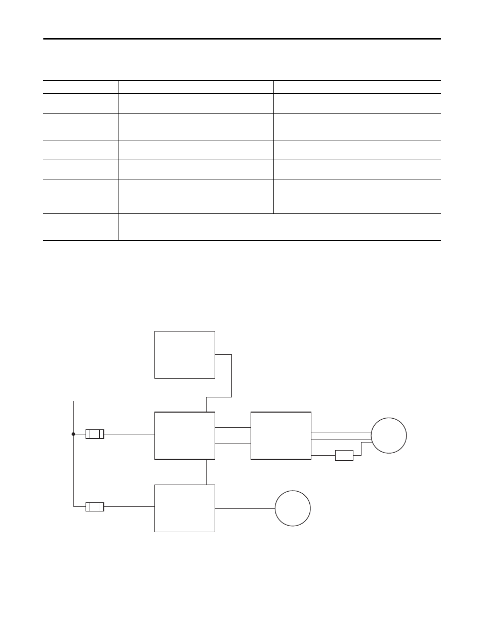
For PowerFlex 700AFE systems, only two frames (10 and 13) are available. The
fan topology is shown here.
Figure 35 - Frame 10 AFE Fan System Topology (Older Style)
Function
AC Fan System
DC Fan System
Dc bus fuses (qty 2)
Early version Bussmann 6 A or present factory installed Ferraz ATQ8
fuses are in the +/- DC bus voltage input at all voltage classes.
Ferraz ATQ8 fuses are in the +/- DC bus voltage input at all voltage classes.
Fan motor
The 230V, three-phase, 225 W, 50 Hz, AC fan motor operates at 2700
RPM and 474 CFM (806 CMH) to provide cooling airflow to the power
structure.
The 48V, 135 W, DC fan motor operates at 2360 RPM and 474 CFM (806
CMH) to provide cooling airflow to the power structure.
Power conditioning magnetics
An isolation transformer and snubber network are present to filter
the PWM switching waveform on the fan motor and fan capacitor.
N/A
Fan capacitor
A 7 uF capacitor provides a phase shift that helps to start the fan
motor and then to regulate the fan motor speed.
N/A
Fan control circuit board
Fan inverter circuit board - where the DC input voltage in converted
to a 50 Hz PWM signal for controlling the fan speed. This circuit board
also contains the on/off fan control signal and fan system fault
detection.
Fan inverter circuit board - where the DC input voltage in converted to
48 VDC for controlling the fan speed. This circuit board also contains the
on/off fan control signal and fan system fault detection.
ASIC circuit board
The ASIC circuit board provides fan control signal at connector X8 on the first fan inverter circuit board. Fan systems can be cascaded by connecting
X3 to X8 of the next fan inverter circuit board. The fan inverter circuit board needs a terminating or loop back plug installed at connector X3 of the
last fan system to provide individual fan system status, for fault detection.
+/- DC Bus
Fuse
AC Fan Inverter
Circuit Board
(Power Structure
Section)
Power
Conditioning
AC Fan
Fuse
DC Fan
ASIC Circuit
Board
X2
X8
X4
X5
X3
X11
DC Fan Power Supply
Circuit Board
(LCL Filter Section)