Rockwell Automation 20Y PowerFlex 700H, 700S, and 700AFE Drive Fan Systems, Frames 9...14 User Manual
Page 164
164
Rockwell Automation Publication PFLEX-IN029B-EN-P - August 2014
Chapter 5
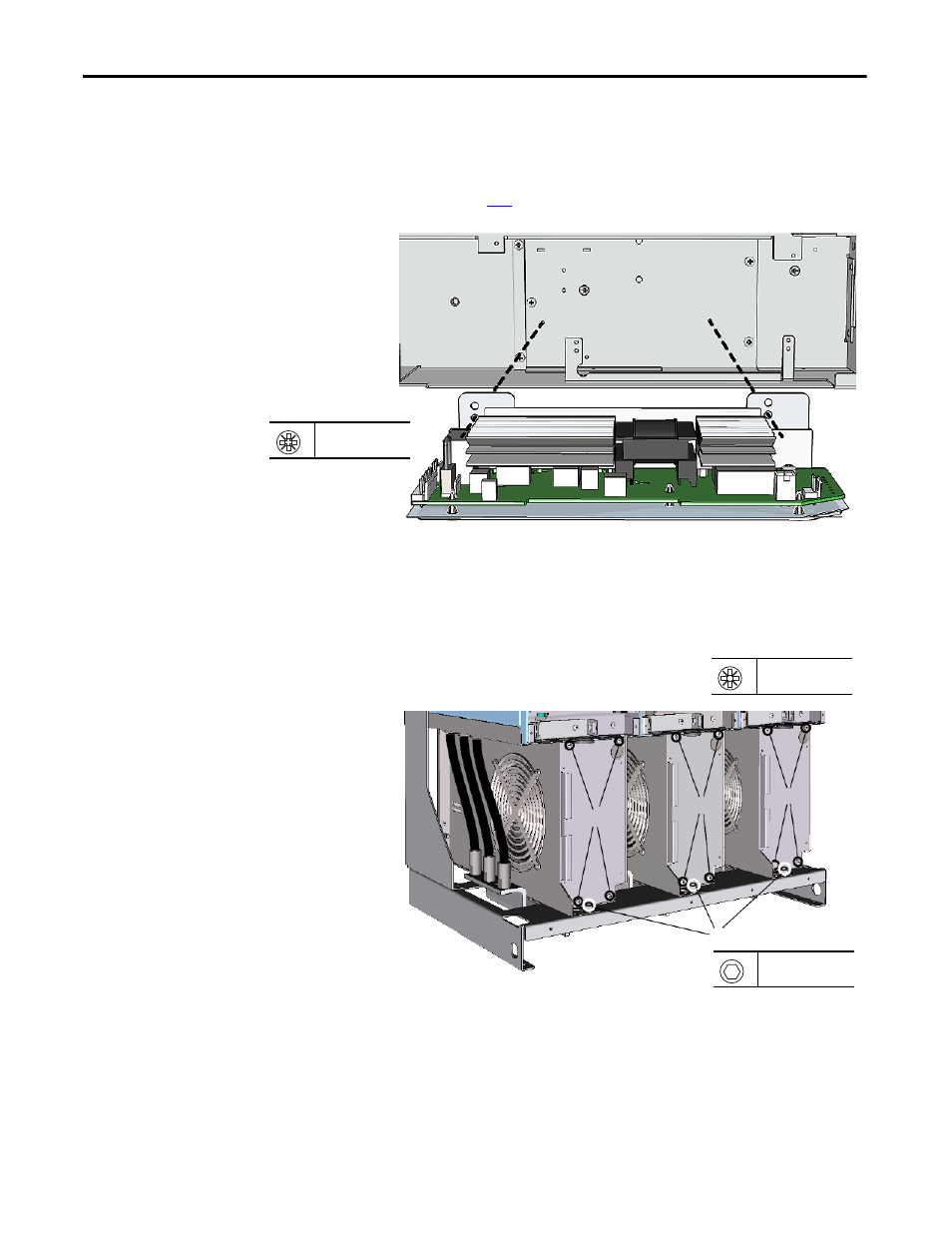
PowerFlex 700H and 700S Drives - Frame 13 Procedures
13.
Install the DC fan inverter assemblies in the converter using the two
M4 x 8 mm POZIDRIV screws supplied in the kit. See Main AC Fan
Inverter Circuit Board (20-VB00299) and DC Fan Power Supply Circuit
Board (SK-H1-DCFANBD1) Removal and Installation (Converter
Only) on page
for details.
14.
Install the main DC fans in the drive using the four M5 x 10 mm
POZIDRIV screws.
15.
Install the M8 x 20 mm hexagonal socket screws supplied with the kit in
front of the main fans.
16.
Connect the fan power supply cables to the connectors on the support
brackets on the drive chassis.
13
PZ2
3.5 N
•
m (31.0 lb
•
in)
DC Fan System
PZ2
3.5 N
•
m (31.0 lb
•
in)
14
14
14
15
14
5.5 mm or HOP6 bit
20 N
•
m (177 lb
•
in)
Note: Inverter section shown