Remove the main fan assembly – Rockwell Automation 20Y PowerFlex 700H, 700S, and 700AFE Drive Fan Systems, Frames 9...14 User Manual
Page 198
198
Rockwell Automation Publication PFLEX-IN029B-EN-P - August 2014
Chapter 7
PowerFlex 700AFE Drive - Frame 10 Procedures
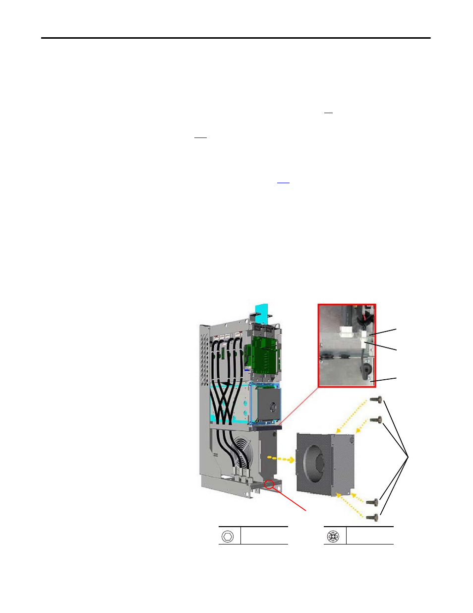
Remove the Main Fan Assembly
The main fan assembly must be removed to gain access to the fan inverter circuit
board. Follow these steps to remove the main fan assembly.
1.
Review the General Precautions on page
2.
Remove power from the AFE. See Remove Power from the AFE on page
3.
If applicable, move the control frame, and remove the screens, airflow
plate, and protective covers from the AFE. See Move the Control Frame,
and Remove the Screens, Airflow Plate, and Protective Covers (IP21 -
Rittal Enclosure) on page
4.
Disconnect the main fan supply connector from the connector on the
support bracket and pull the connector out of the sheet metal support
bracket.
5.
Remove the M8 x 20 mm hexagonal socket screw from the chassis in front
of the fan housing in order to allow room for the fan housing to be
removed from the unit.
6.
Remove the four M5 x 10 POZIDRIV screws that secure the main fan
housing to the assembly and remove the fan housing.
7.
Install the main cooling fan assembly in the reverse order of removal.
4
6
5
5.5 mm or HOP6 bit
20 N
•
m (177 lb
•
in)
PZ2
3.5 N
•
m (31.0 lb
•
in)
Front of
main fan
housing
Support
bracket