Figure 25 – Rockwell Automation 20Y PowerFlex 700H, 700S, and 700AFE Drive Fan Systems, Frames 9...14 User Manual
Page 216
216
Rockwell Automation Publication PFLEX-IN029B-EN-P - August 2014
Chapter 7
PowerFlex 700AFE Drive - Frame 10 Procedures
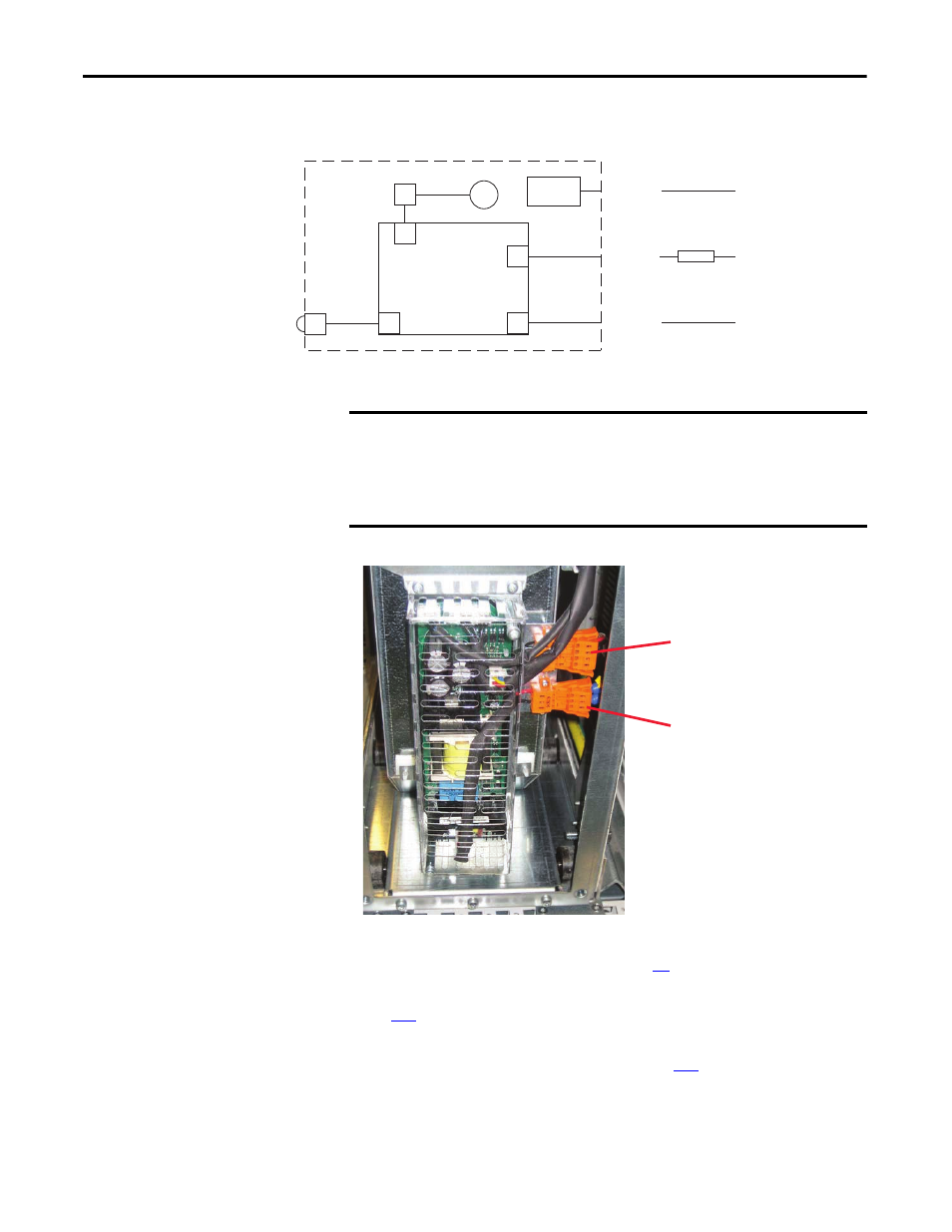
Figure 25 - LCL Filter Fan DC Power Supply (SK-Y1-DCPS1-D460 or SK-Y1-DCPS1-F325) Wiring
Diagram
1.
Review the General Precautions on page
2.
Remove power from the AFE. See Remove Power from the AFE on page
3.
Remove the LCL filter fan assembly from the AFE. See LCL Filter Fan
Assembly Removal and Installation on page
.
X3
X3
LCL Filter
X8
X53 (3-pin)
+ Pin = DC+ (supply)
- Pin = DC- (supply)
X4
X51 (4-pin)
Pin 5 = +16.5V
Pin 3 = (fan control)
Pin 1 = (fan alarm)
Fuse
X52 (4-pin)
Pin 1 = KLIXON
Pin 4 = KLIXON
X1
Fan
KLIXON
X1
Fan DC Power
Supply PCB
AFE Power Structure
X3 on AFE Power Structure
DC Bus
IMPORTANT
Before doing any work, disconnect the AFE power structure from the AC supply,
and wait until the fan stops and the indicators on the keypad turn off. (If a
keypad is not attached, see the indicator through the keypad base.) Wait 5
more minutes before doing any work on the DC-to-DC power supply. Do not
even open the cover until after this time has expired.
X51
X53
Note: Image for SK-Y1-DCPS1-D460
or SK-Y1-DCPS1-F325