Rockwell Automation 20Y PowerFlex 700H, 700S, and 700AFE Drive Fan Systems, Frames 9...14 User Manual
Page 170
170
Rockwell Automation Publication PFLEX-IN029B-EN-P - August 2014
Chapter 5
PowerFlex 700H and 700S Drives - Frame 13 Procedures
4.
Remove the main fan circuit board from the drive. See Main AC Fan
Inverter Circuit Board (20-VB00299) and DC Fan Power Supply Circuit
Board (SK-H1-DCFANBD1) Removal and Installation (Converter
Only) on page
.
5.
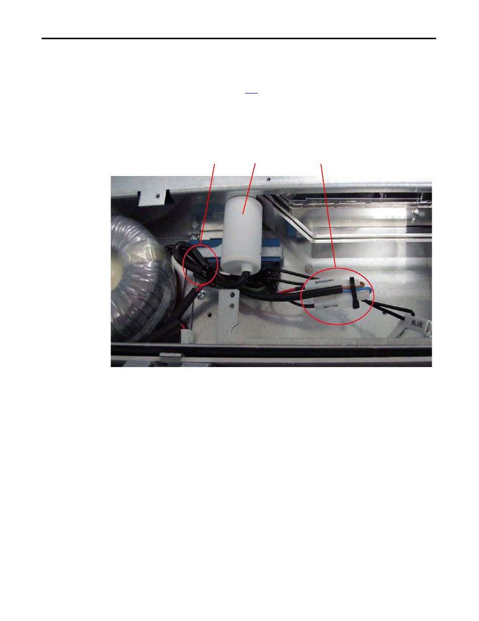
Cut the cable ties that secure the fan capacitor wires to the wire bundle.
6.
Disconnect the capacitor wires from the connectors marked “Blue” and
“Brown”.
7.
Unscrew the capacitor from the drive frame and remove the capacitor.
8.
Install the main fan capacitor in the reverse order of removal.
Main AC Fan Inverter Capacitor (SK-H1-FANCAP-F1314) Removal and
Installation (Inverter Only)
Note: The AC fan inverter capacitor replacement kit (SK-H1-FANCAP-F1314)
contains a new sheet metal bracket, hardware and fasteners, and a series B
capacitor (identified in the table and shown below). The series B capacitor
(50 mm dia. x 62 mm tall) is larger than the series A capacitor (35 mm dia. x 57
mm tall). If a series A capacitor is currently installed, always replace it with the
new series B capacitor.
5
6
7
AC Fan System Converter Section