Rockwell Automation 20Y PowerFlex 700H, 700S, and 700AFE Drive Fan Systems, Frames 9...14 User Manual
Page 52
52
Rockwell Automation Publication PFLEX-IN029B-EN-P - August 2014
Chapter 1
PowerFlex 700H and 700S Drives - Frame 9 Procedures
5.
Remove the two M4 x 40 mm POZIDRIV screws that secure the fan to
the cross-plate and remove the fan. Retain the fan grill plate for reuse.
6.
Install the fan in the reverse order of removal.
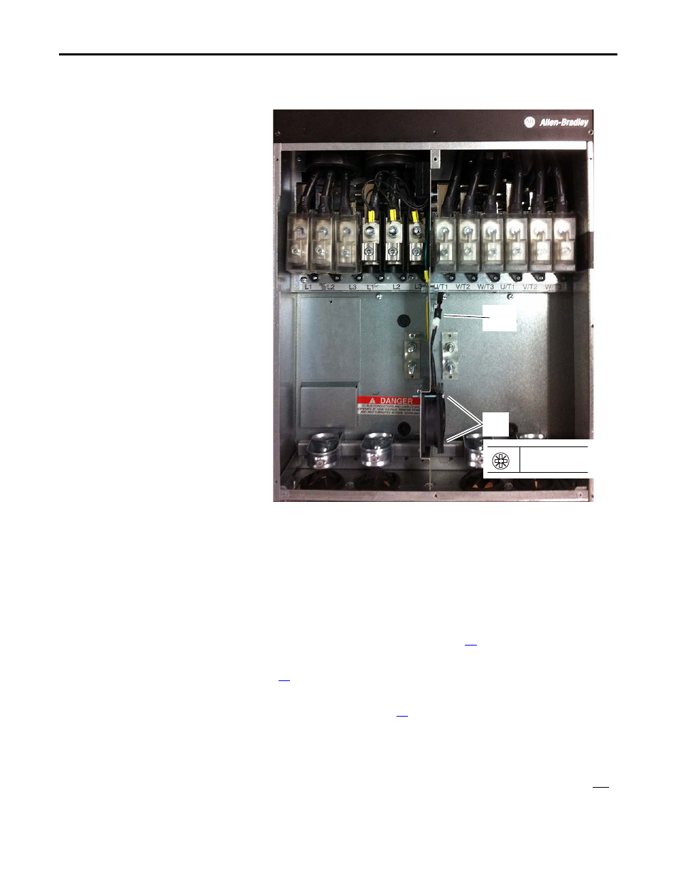
Internal Stirring Fan (20-PP01068) Removal and Installation
Follow these steps to remove and replace the internal stirring fan located on the
drive frame in the lower part of the drive.
1.
Review the General Precautions on page
2.
Remove power from the drive. See Remove Power from the Drive on page
.
3.
Remove the lower protective cover from the drive. See Remove the Lower
Protective Cover on page
.
4.
Remove the covers or protective isolation barriers from the U/T1, V/T2,
and W/T3 power terminals.
5.
Remove the M8 nut and washer that secure the U/T1, V/T2, and
W/T3 power wires to the terminals, to loosen the wires only. You do not
need to remove the external wires from the terminals.
4
5
PZ2
3.0 N
•
m (27 lb
•
in)