Rockwell Automation 20Y PowerFlex 700H, 700S, and 700AFE Drive Fan Systems, Frames 9...14 User Manual
Page 160
160
Rockwell Automation Publication PFLEX-IN029B-EN-P - August 2014
Chapter 5
PowerFlex 700H and 700S Drives - Frame 13 Procedures
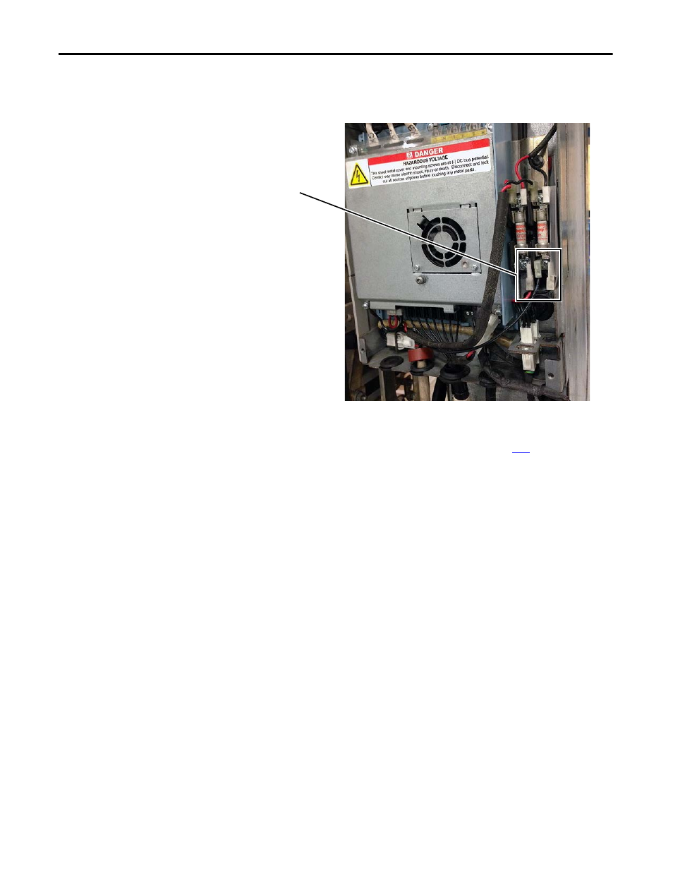
10.
Connect the fan inverter power supply wires to the bottom of the fuse
holders. Note that the red wire (+DC) is connected to the left side
terminal and the black wire (-DC) is connected to the right side terminals.
11.
Install the new main DC fans in the fan housings using the M5 x 10 mm
POZIDRIV screws supplied in the kit. Final torque is 3.5 N
•
m (31.0
lb
•
in). See Remove the Main Fan Assembly on page
for details.
12.
Install the M8 x 20 mm hexagonal socket screws supplied with the kit in
the front of the main fans. Final torque is 20 N•m (177 lb•in).
13.
Connect the fan power supply cables to the connectors on the support
brackets on the main chassis.
5