Rockwell Automation 20Y PowerFlex 700H, 700S, and 700AFE Drive Fan Systems, Frames 9...14 User Manual
Page 273
Rockwell Automation Publication PFLEX-IN029B-EN-P - August 2014
273
PowerFlex 700H and 700S Diagnostic Procedures
Appendix A
Logic Power:
DC bus voltage is connected to X2 on the AC or DC fan inverter
board, which is routed to the SMPS that develops the logic power on the circuit
board and DC bus to the “H” bridge.
Fault Detection:
The AC or DC fan inverter board contains the fault detection
scheme which includes current, temperature, and DC bus voltage feedback
systems. A shunt resistor in the H-bridge provides current feedback, a NTC on
the board provides temperature feedback, and a resistive-based voltage divider
provides DC bus voltage feedback. These systems are summed in the
microprocessor with an output status signal “fan alarm.”
The microprocessor “fan alarm” signal is logically NANDed with the “fan alarm
next” signal (X3, pin 4) and optically isolated to provide a fan status to the next
fan inverter board at X8, pin 4, and pins 6 and 7, where a low signal is active and a
high signal is faulted. If this is the first AC or DC fan inverter board, this fan
alarm status output goes to the ASIC board. On the last fan inverter board in
series, X3, pins 2 and 4 must be connected together to pull up the next fan alarm
signal.
Fan control:
The fan control signal originates on the ASIC circuit board and
enters at X8, pin 3, and is optically isolated, before being routed to the
microprocessor. When the fan control signal (X8, pin 3) is pulled low, the next
fan control (X3, pin 1) is also pulled low, and the microprocessor fan control is
enabled.
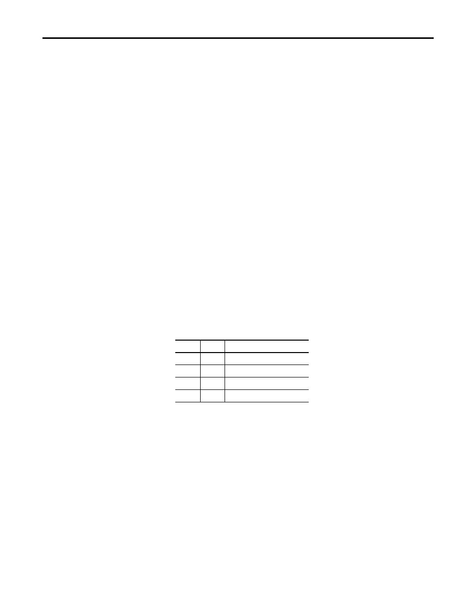
For the AC fan inverter system, the fan control is defined by the switch states as a
50 Hz, 230V AC motor for frames 9…14 drives and the inverter section of the
frame 10 and 13 AFE.
For the DC fan inverter system, the fan control serves to either enable or disable
the main DC motor in the cooling fan.
PWM gate signals and fan power:
If the fault detection status is OK and the fan
control is enabled, then the microprocessor will generate the PWM signals to the
gate drive circuitry and control the H bridge.
For the AC fan system, the PWM signal is a 50 Hz fundamental sinewave at the
fan output terminals (X4 and X5). The AC fan inverter board output energizes
the isolation transformer before supplying two of the three phases to the fan
motor. The third phase is sourced through the 7
μF capacitor which provides the
phase shift to start rotation and help to control the fan speed.
The DC fan system uses a 48V DC output that energizes the DC fan motor.
Switch
Setting
To indicate the following:
S1
Off
50 Hz fan motor frequency
S2
Off
220 V AC motor voltage
S3
On
230 V AC motor voltage
S4
Off
Frame size 9…14