Rockwell Automation 20Y PowerFlex 700H, 700S, and 700AFE Drive Fan Systems, Frames 9...14 User Manual
Page 266
266
Rockwell Automation Publication PFLEX-IN029B-EN-P - August 2014
Appendix A
PowerFlex 700H and 700S Diagnostic Procedures
4.
Remove the main fan inverter assemblies. See Remove the Main AC or
DC Fan Power Supply Assemblies on page
Isolate the Left-side Fan Inverter
5.
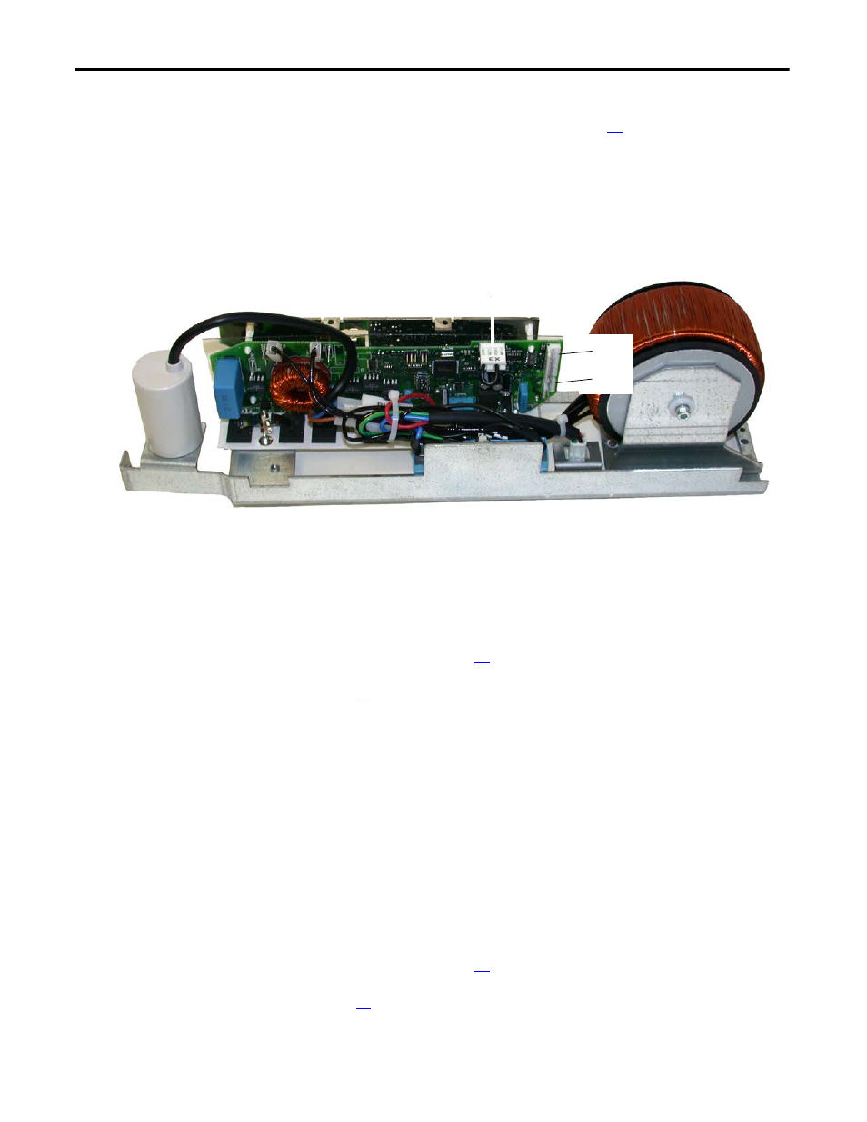
Disconnect the cable from connector X3 of the left-side fan inverter.
6.
Remove the jumper from connector X3 of the right-hand inverter, and
install it on connector X3 of the left-hand inverter.
7.
Energize the drive.
If the left-side fan runs, then the right-side fan inverter circuit board is
faulty and needs to be replaced. For AC fan systems, see Main AC Fan
Inverter Circuit Board (20-VB00299) and AC Fan Output Transformer
Assembly [20-FR10844 (Left) or 20-FR10845 (Right)] Removal and
Installation on page
. For DC fan systems, see Main DC Fan Power
Supply System (SK-H1-DCFANBD1) Removal and Installation on page
.
Isolate the Right-side Fan Inverter
8.
Connect all cables in the original configuration.
9.
Disconnect the cable from connector X8 on the right-side fan inverter.
10.
Disconnect the cable from connector X8 on the left-side fan inverter and
connect it to connector X8 on the right-side fan inverter.
11.
Energize the drive.
If the right-side fan runs, then the left-side fan inverter circuit board is
faulty and needs to be replaced. For AC fan systems, see Main AC Fan
Inverter Circuit Board (20-VB00299) and AC Fan Output Transformer
Assembly [20-FR10844 (Left) or 20-FR10845 (Right)] Removal and
Installation on page
. For DC fan systems, see Main DC Fan Power
Supply System (SK-H1-DCFANBD1) Removal and Installation on page
.
X3 (jumper installed)
Right-side AC fan inverter shown
X8
X2