Rockwell Automation 20Y PowerFlex 700H, 700S, and 700AFE Drive Fan Systems, Frames 9...14 User Manual
Page 79
Rockwell Automation Publication PFLEX-IN029B-EN-P - August 2014
79
PowerFlex 700H and 700S Drives - Frame 10 Procedures
Chapter 2
5.
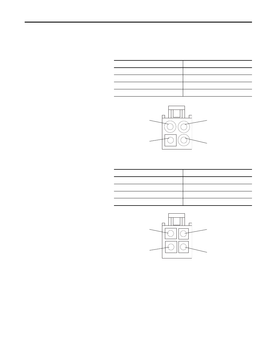
Using the appropriate table below, measure the resistance between the fan
supply wires.
AC Fan
: If the measurements are not similar to those in this table, replace
the AC fan.
DC Fan
: If the measurements are not similar to those in this table, replace
the DC fan.
Connection wires
Resistance ±5%
Black-Brown
62
Ω
Brown-Blue
36
Ω
Blue-Black
27
Ω
Green-chassis
0
Ω
Connection wires
Resistance ±5%
Red-Blue
∞ Ω
Red-White
∞ Ω
White-Yellow
∞ Ω
Blue-White
∞ Ω
Blue (Motor) Pin 4
Green/Yellow (Ground) Pin 1
Brown (Motor) Pin 3
Black (Motor) Pin 2
AC Fan Pinouts
White (Tach Output) Pin 3
Red (+) Pin 1
Blue (-) Pin 4
Yellow (Control Output) Pin 2
DC Fan Pinouts