Figure 10, Nfe 3, Nfe 2 – Rockwell Automation 20Y PowerFlex 700H, 700S, and 700AFE Drive Fan Systems, Frames 9...14 User Manual
Page 126: Nfe 1
126
Rockwell Automation Publication PFLEX-IN029B-EN-P - August 2014
Chapter 5
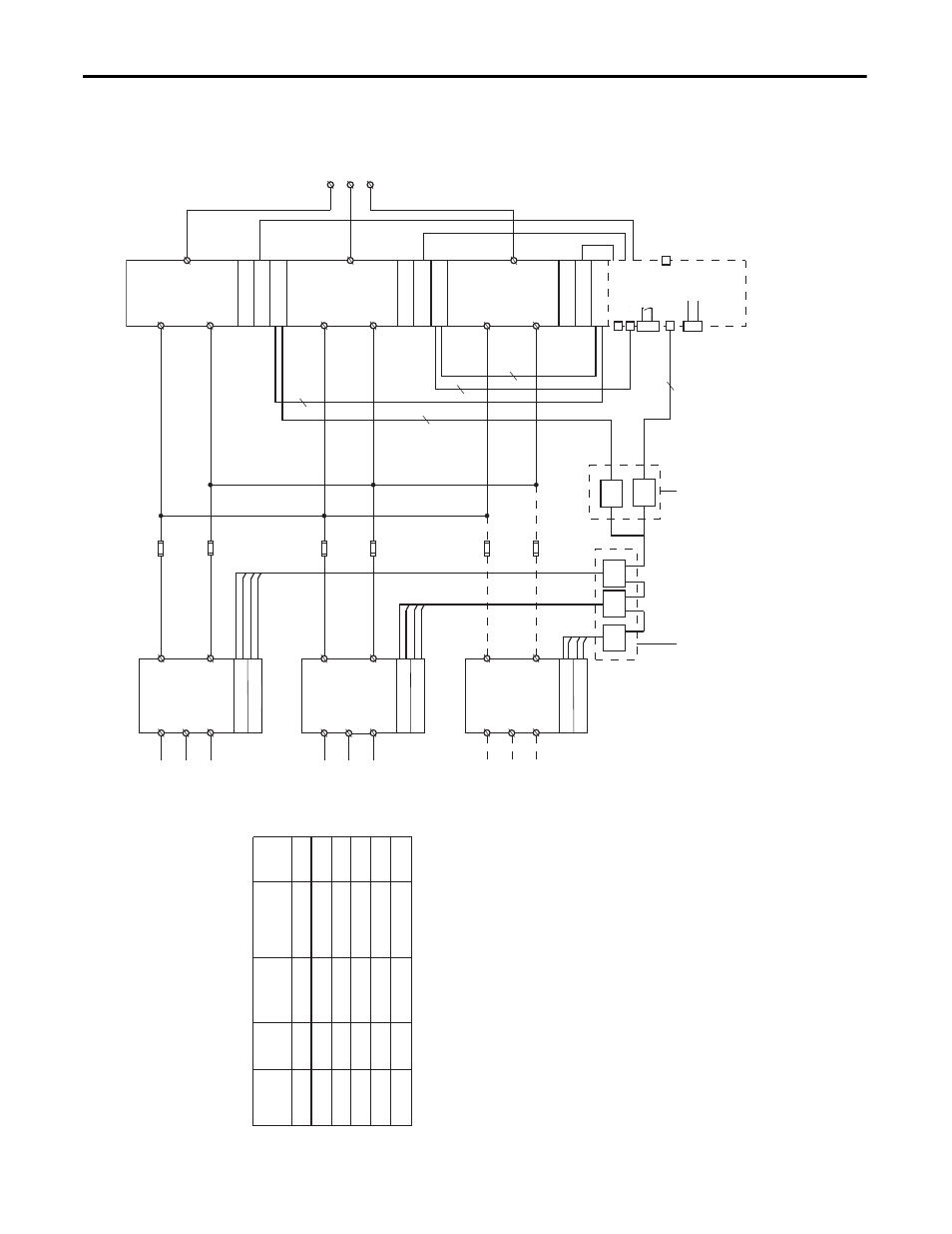
PowerFlex 700H and 700S Drives - Frame 13 Procedures
Figure 10 - Frame 13 AC Input Drive Converter and Inverter Sections
Fa
n
Rectifier Bd.
L1
L3
L2
NFE 3
(1)
X3 X8
X6
X201
Fa
n
Rectifier Bd.
L1
L3
L2
NFE 2
(1)
X3 X8
X6
X201
Fa
n
Rectifier Bd.
L1
L3
L2
NFE 1
(1)
X3 X8
X6
X201
F10
F11
DC+
DC-
X1
X1
X1
F
an Distr
ib
ution
Bloc
k (Located in
U Phase)
F12
F13
DC+
DC-
DC+
DC-
F14
F15
5
25
26
21
22
23
X9
+24V
0EV
A
X15
Charge
Rela
y
X2
Fa
n
Gate Dr
iv
er
Measure L/R
X5
X4
X3
X11
Fa
n
Gate Dr
iv
er
Measure L/R
Fa
n
Gate Dr
iv
er
Measure L/R
Phase
Module
W
Phase
Module
V
Phase
Module
U
X3
X8
X3
X8
X3
X8
X1
X1
X1
4
3
3
4
U /
T1
V /
T2
W /
T3
ASIC
Board
(1)
The n
umber of NFE’
s v
ar
ies with the dr
iv
e
r
ating as sho
wn in this tab
le:
V
oltage
Class
Amps
# of
Reactors
Reactor
Connection
# of
NFEs
400
400
400
600
600
600
1150
1300
1450
920
1030
1180
2
3
3
2
2
2
X2
X2
X2
X3
X3
X3
2
3
3
2
2
2
DC+
DC-
DC+
DC-
DC+
DC-
F
an Supply Connection
(Located on the front
of each Con
v
er
ter)
X3
X2