Rockwell Automation 20Y PowerFlex 700H, 700S, and 700AFE Drive Fan Systems, Frames 9...14 User Manual
Page 210
210
Rockwell Automation Publication PFLEX-IN029B-EN-P - August 2014
Chapter 7
PowerFlex 700AFE Drive - Frame 10 Procedures
13.
Complete the remaining installation in the reverse order of removal.
Main AC Fan (20-FI13300) and Main DC Fan (SK-Y1-DCFAN1) Assembly Removal and
Installation
Follow these steps to measure the resistance between the main fan supply wires
and remove and replace the main fan, if necessary.
Notes:
•
The DC fan replacement kit only contains the fan motor and impeller
assembly. Therefore, the sheet metal housing for the fan must be reused.
•
To identify which fan is installed in your drive, see Fan Inverter System
Block Diagrams on page
.
1.
Review the General Precautions on page
2.
Remove power from the AFE. See Remove Power from the AFE on page
3.
If applicable, move the control frame, and remove the screens, airflow
plate, and protective covers from the AFE. See Move the Control Frame,
and Remove the Screens, Airflow Plate, and Protective Covers (IP21 -
Rittal Enclosure) on page
4.
Remove the main fan assembly from the AFE. See Remove the Main Fan
Assembly on page
.
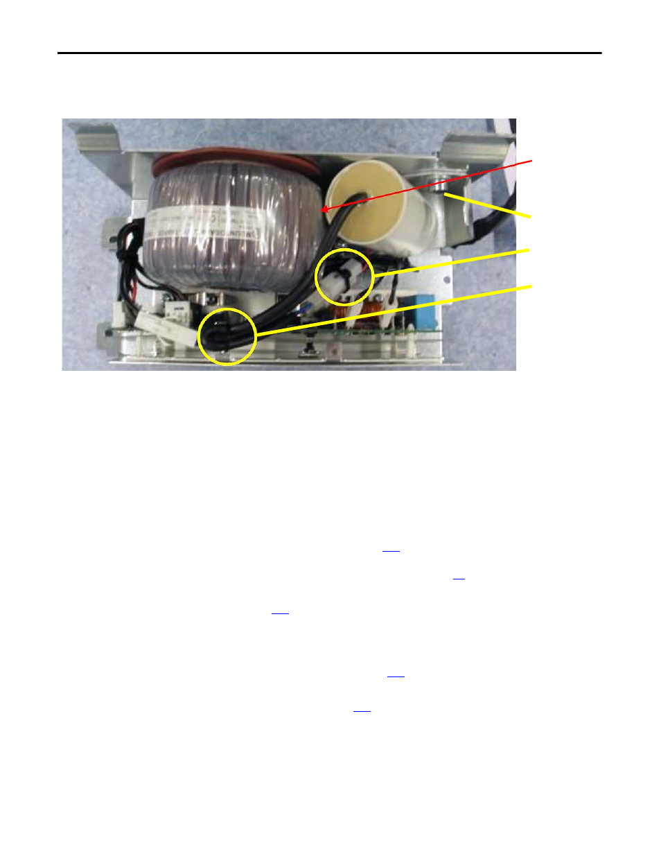
IMPORTANT: Verify
that the fan capacitor
does not touch the
fan transformer.
10
11
12
AC fan inverter system shown.