Rockwell Automation 20Y PowerFlex 700H, 700S, and 700AFE Drive Fan Systems, Frames 9...14 User Manual
Page 47
Rockwell Automation Publication PFLEX-IN029B-EN-P - August 2014
47
PowerFlex 700H and 700S Drives - Frame 9 Procedures
Chapter 1
9.
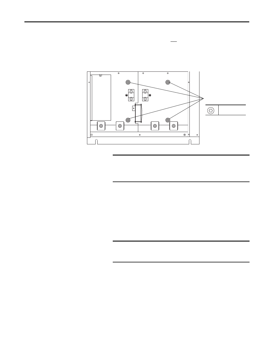
Using the 9 cm long T20 hexalobular screwdriver, loosen (approximately
12 full screw rotations), but do not remove the four screws (accessible
through the holes vacated by the rubber bushings) so that the fan assembly
can be removed from the drive. Note: These screws secure a sheet metal
plate against the fan assembly inside the drive chassis, effectively sealing the
fan plenum chamber.
10.
Remove the four M5 x 10 mm POZIDRIV screws that secure the fan
assembly to the bottom of the drive chassis and slide the fan assembly
down and out of the drive.
If the fan assembly does not easily come out of the dive chassis, loosen the
front screws (as instructed in step 9) another turn and attempt to remove
the fan assembly again. Continue loosening the screws until the fan
assembly slides easily from the drive.
9
T20
3.0 N
•
m (27 lb
•
in)
IMPORTANT
The next step assumes that the drive is mounted in a vertical position.
Once the screws that secure the main fan assembly to the drive are
loosened, the fan will be free to slide out of the bottom of the drive
chassis. Support the fan assembly when the screws are loosened.
IMPORTANT
Do not attempt to force the fan plate from the drive. This may bend the
fan and surrounding sheet metal. The sheet metal bracket must be
reused.