Rockwell Automation 20Y PowerFlex 700H, 700S, and 700AFE Drive Fan Systems, Frames 9...14 User Manual
Page 72
72
Rockwell Automation Publication PFLEX-IN029B-EN-P - August 2014
Chapter 2
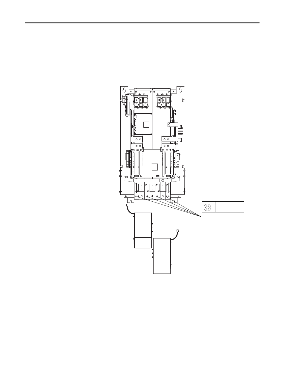
PowerFlex 700H and 700S Drives - Frame 10 Procedures
5.
Remove the two M6 x 20 mm hexalobular screws that secure each of the
main AC fan housings to the drive and remove the fan assemblies.
Note: The back of the fan housing contains two holes in the sheet metal
that fit onto positioning pins located on the drive frame. To remove the
main fan assemblies, lower the front end of the assembly downward in
order to clear the sheet metal on the frame, and pull the fan assembly off
the positioning pins and out of the drive.
6.
Install the new DC main fan assemblies in the reverse order of removal as
instructed in step
.
5
T30
3.0 N
•
m (26.5 lb
•
in)
This manual is related to the following products: