Frame 9 schematic diagrams – Rockwell Automation 20Y PowerFlex 700H, 700S, and 700AFE Drive Fan Systems, Frames 9...14 User Manual
Page 21
Rockwell Automation Publication PFLEX-IN029B-EN-P - August 2014
21
PowerFlex 700H and 700S Drives - Frame 9 Procedures
Chapter 1
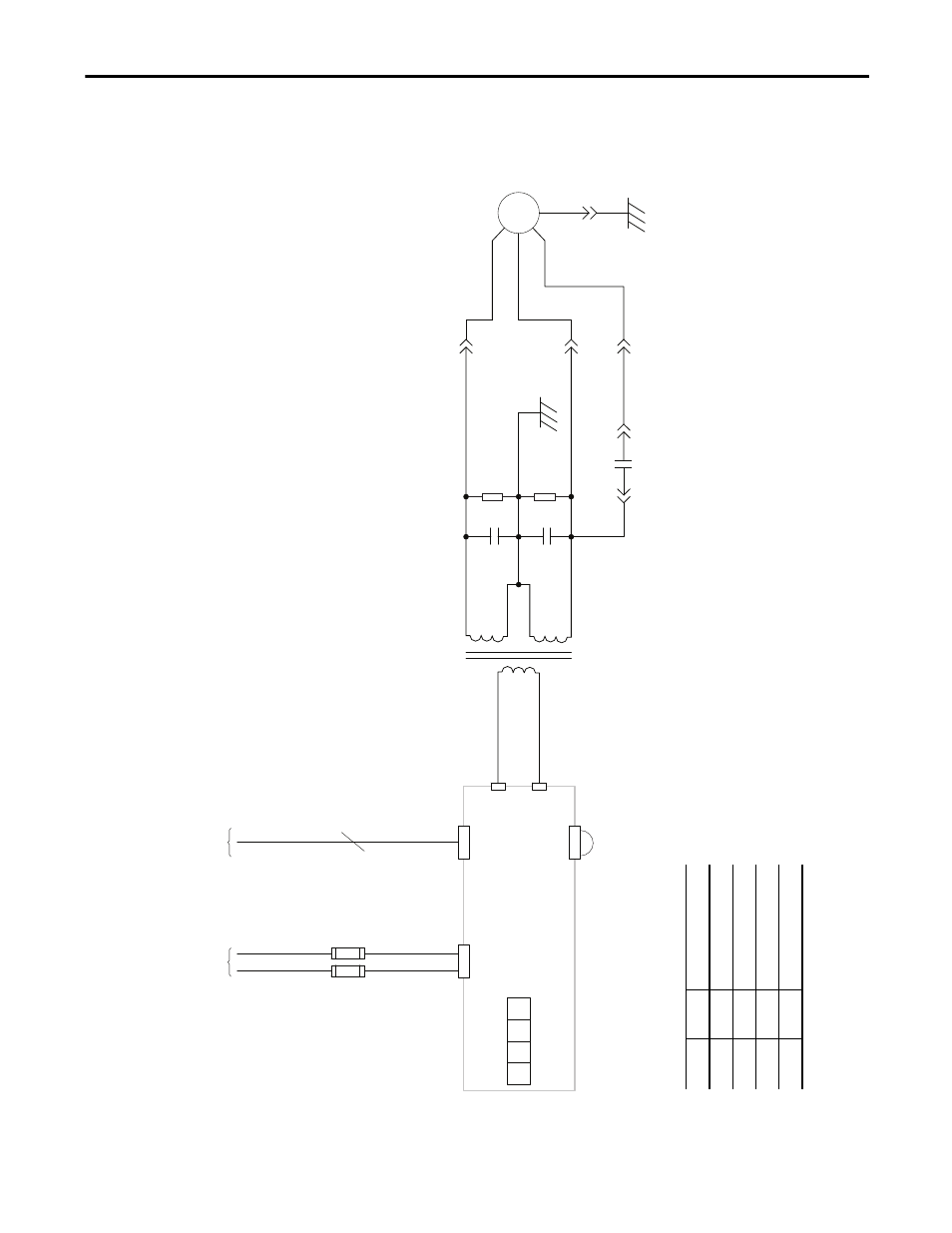
Frame 9 Schematic Diagrams
Figure 2 - Frame 9 AC Fan System Wiring Schematic Diagram
X8
F2
X2
4
Fan Frequency
Converter
+-
Off
S1-1
Off
S1-2
On
S1-3
Off
S1-4
S1 - Setup Switch
F1
Fr
om P
ow
er
Boar
d X10
Fr
om P
ow
er
Boar
d X7
M1
Brown
Black
Blue
Main Fan
M
Black 6
Black 5
Black 4
Black 3
Black 2
Black 1
X4
X5
2.2
µf
10 M
Ω
2.2
µf
10 M
Ω
Yellow/Green
7 µ
f
X3
Install Jumper on
400/480V AC input drives only
(Not present on fan inverter
circuit boards, cat. no. VB00399)
Swi
tch
Setting
To indi
ca
te the
fo
llo
wing:
S1
Off
50
Hz f
an m
ot
or fr
eq
uenc
y
S2
O
ff
220 V
A
C m
ot
or v
oltag
e
S3
O
n
230 V
A
C m
ot
or v
oltag
e
S4
O
ff
Fr
am
e si
ze
9…
14
This manual is related to the following products: