Rockwell Automation 20Y PowerFlex 700H, 700S, and 700AFE Drive Fan Systems, Frames 9...14 User Manual
Page 137
Rockwell Automation Publication PFLEX-IN029B-EN-P - August 2014
137
PowerFlex 700H and 700S Drives - Frame 13 Procedures
Chapter 5
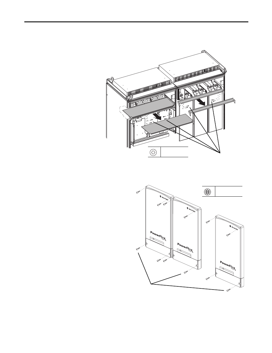
6.
Remove the four hexalobular screws that secure the air flow plate to the
drive enclosure and slide the plate off the drive.
7. If necessary, remove the four M5 x 16 mm POZIDRIV screws that
secure the two or three protective covers to the drive, then remove the
covers.
8. Replace the control frame, screens, airflow plates, and protective covers
in the reverse order of removal.
5
Converter unit
Inverter unit
Note: AC input drive shown
T20
3.0 N
•
m (27 lb
•
in)
DC
BUS CONDUCT
ORS
AND
C
AP
AC
ITORS
OPERA
TE
AT
HIG
H V
OL
TAGE.
R
EMO
VE
PO
WER
AND
WA
IT 5 M
INUTES
BE
FORE SER
VIC
ING
DA
NG
ER
!
DC B
US
C
ONDUCT
ORS
AND CAP
ACIT
ORS
OPERA
TE
AT
H
IGH
VOL
TAG
E. R
EMO
VE PO
WER
AND
WA
IT 5
MIN
UTES
BEFORE SER
VIC
ING
DANGER
!
DC B
US CONDUCT
ORS
AND CAP
AC
ITORS
OPERA
TE
AT H
IG
H V
OL
TAGE.
R
EMO
VE PO
WER
AND
W
AIT
5 M
IN
UTES
BEFORE SER
VIC
IN
G
DANGER
!
2 or 3 covers
6
PZ2
1.65 N
•
m (14.6 lb
•
in)