Rockwell Automation 20Y PowerFlex 700H, 700S, and 700AFE Drive Fan Systems, Frames 9...14 User Manual
Page 50
50
Rockwell Automation Publication PFLEX-IN029B-EN-P - August 2014
Chapter 1
PowerFlex 700H and 700S Drives - Frame 9 Procedures
8.
Remove the two M5 x 10 POZIDRIV screws that secure the output
transformer to the drive frame.
9.
While pushing the output transformer wires and rubber bushing through
the hole in the back of the fan inverter compartment, remove the output
transformer from the bottom of the drive.
10.
Install the new output transformer assembly in the reverse order of
removal.
Chassis Stirring Fan (20-PP01068) Removal and Installation
Note: The chassis stirring fan is only installed on PowerFlex 700S Phase II drives.
Follow these steps to remove and replace the chassis stirring fan.
1.
Review the General Precautions on page
2.
Remove power from the drive. See Remove Power from the Drive on page
.
3.
Remove the upper protective cover from the drive. See Remove the Upper
Protective Cover on page
.
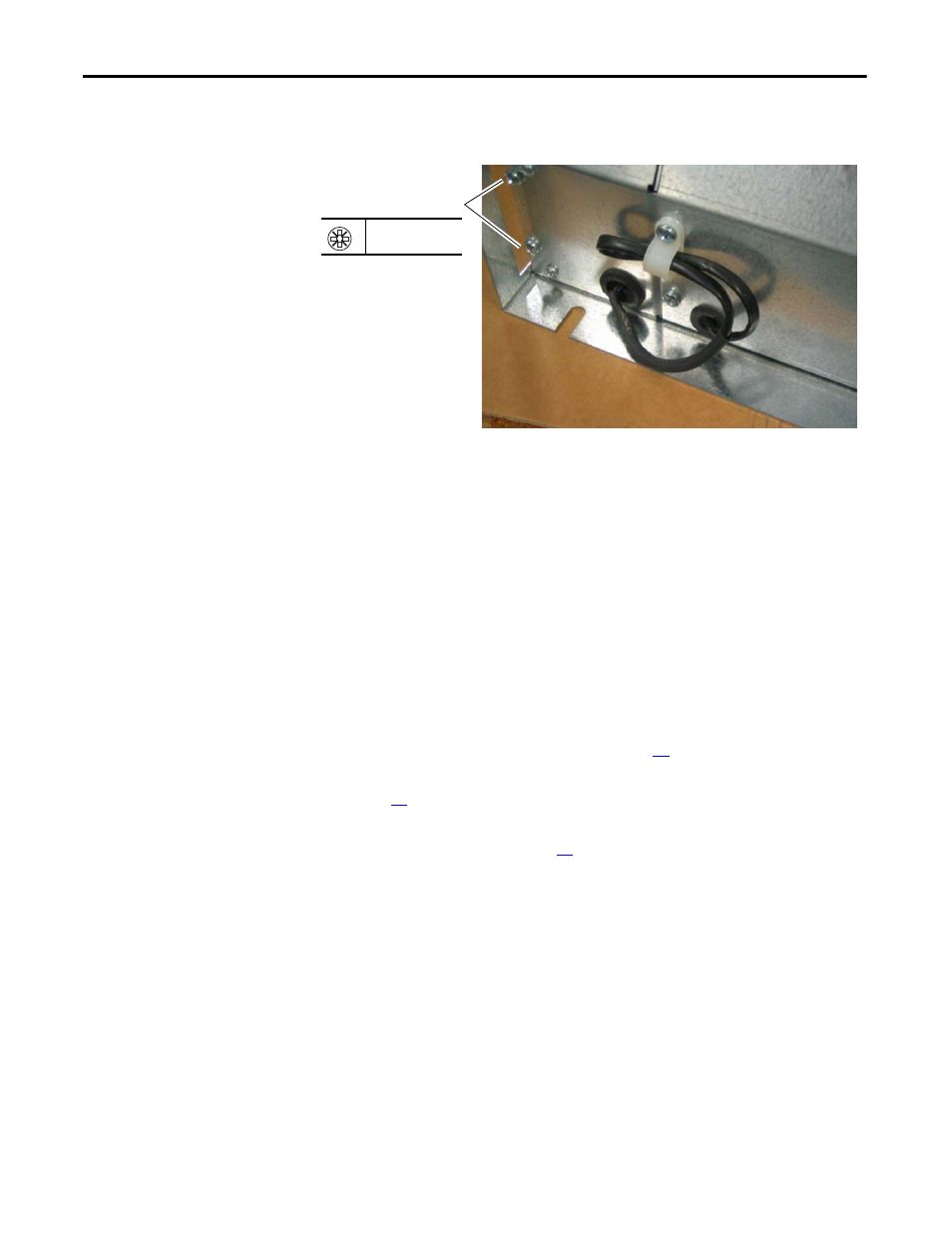
4.
Disconnect the fan power cable from connector J18 on the power interface
circuit board.
8
PZ2
4.0 N
•
m (35 lb
•
in)