Chapter 7, Powerflex 700afe drive - frame 10 procedures, Chapter – Rockwell Automation 20Y PowerFlex 700H, 700S, and 700AFE Drive Fan Systems, Frames 9...14 User Manual
Page 185
Rockwell Automation Publication PFLEX-IN029B-EN-P - August 2014
185
Chapter
7
PowerFlex 700AFE Drive - Frame 10 Procedures
This chapter contains spare part information and procedures for testing and
replacing fan system components for frame 10 PowerFlex 700AFE drives. See
Appendix A PowerFlex 700H and 700S Diagnostic Procedures on page
for
additional component test procedures.
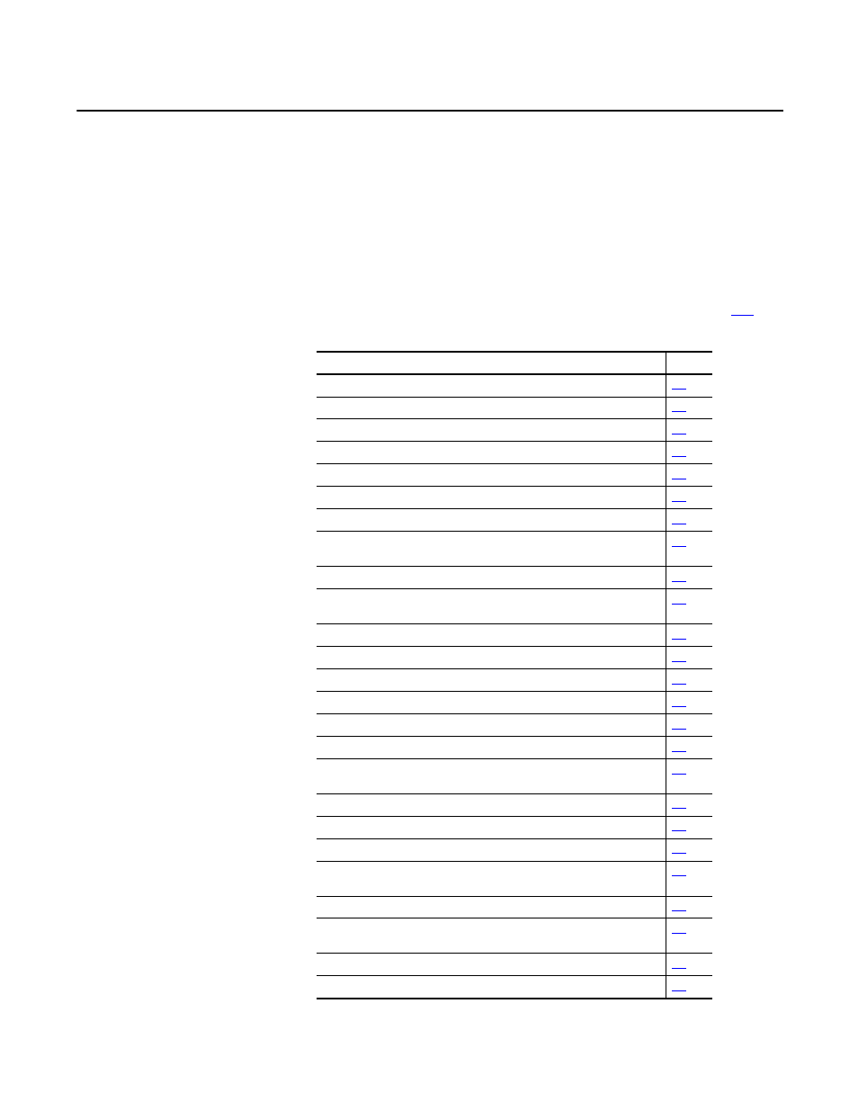
Topic
Page
Frame 10 AFE Drive Configurations
Frame 10 AFE Fan System Spare Parts
Tools Needed for Frame 10 AFE Fan System Repairs
Frame 10 AFE Fan System Schematic Diagrams
Frame 10 AFE Fan System Replacement Procedures
ASIC Circuit Board Assembly Cooling Fan (20-PP01096) Removal and Installation
AC or DC Fan Inverter Fuses (20-PP20202) and Fuse Holder (20-PP20300) Removal
and Installation
AC Fan Inverter Assembly (20-FI13301) Removal and Installation
Main AC Fan Inverter Circuit Board (20-VB00299) Removal and Installation
Main DC Fan Power Supply Circuit Board (SK-H1-DCFANBD1) Removal and Installation
AC to DC Main Fan System (SK-Y1-DCFANRETROFIT-F10) Retrofit
Main AC Fan Inverter Capacitor (SK-H1-FANCAPF1314) Removal and Installation
Main AC Fan (20-FI13300) and Main DC Fan (SK-Y1-DCFAN1) Assembly Removal and
Installation
Removing the LCL Filter Protective Cover
LCL Filter DC Fan Fuses (20-PP20202) Removal and Installation
LCL Filter Fan DC Power Supply (SK-Y1-DCPS1-D460 or SK-Y1-DCPS1-F325) Removal
and Installation
LCL Filter DC Fan Power Supply Kit (SK-Y1-DCPS2-F10) Removal and Installation
LCL Filter DC Fan Power Supply Circuit Board (SK-H1-DCFANBD1) Removal and
Installation
LCL Filter Fan Assembly Removal and Installation
LCL Filter Main DC Fan (SK-Y1-DCFAN1) Assembly Removal and Installation