Rockwell Automation 20Y PowerFlex 700H, 700S, and 700AFE Drive Fan Systems, Frames 9...14 User Manual
Page 150
150
Rockwell Automation Publication PFLEX-IN029B-EN-P - August 2014
Chapter 5
PowerFlex 700H and 700S Drives - Frame 13 Procedures
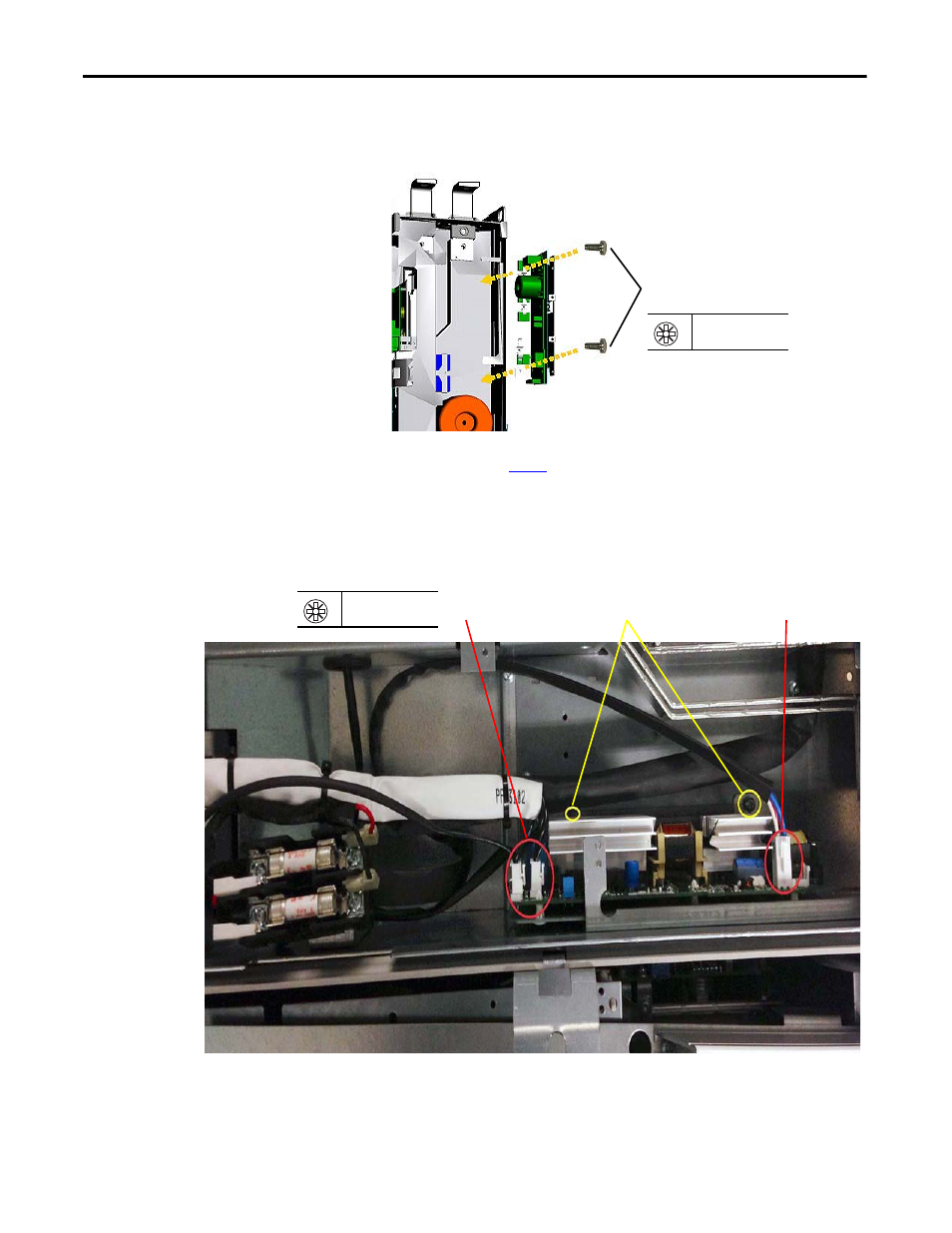
c. Remove the two M4 x 8 mm POZIDRIV screws that secure the AC fan
circuit board to the drive frame and carefully remove the circuit board.
d.
6.
Disconnect the cable from connector X2, X3, X8, and X81 on the DC fan
circuit board.
7.
Remove the two M4 x 8 mm POZIDRIV screws that secure the main DC
fan circuit board to the drive frame and carefully remove the circuit board.
8.
Install the fan circuit board in the reverse order of removal.
c.
PZ2
3.0 N
•
m (27.0 lb
•
in)
6
6
7
PZ2
3.0 N
•
m (26.5 lb
•
in)
Converter section
with DC fan system
This manual is related to the following products: