Rockwell Automation 20Y PowerFlex 700H, 700S, and 700AFE Drive Fan Systems, Frames 9...14 User Manual
Page 254
254
Rockwell Automation Publication PFLEX-IN029B-EN-P - August 2014
Chapter 8
PowerFlex 700AFE Drive - Frame 13 Procedures
6.
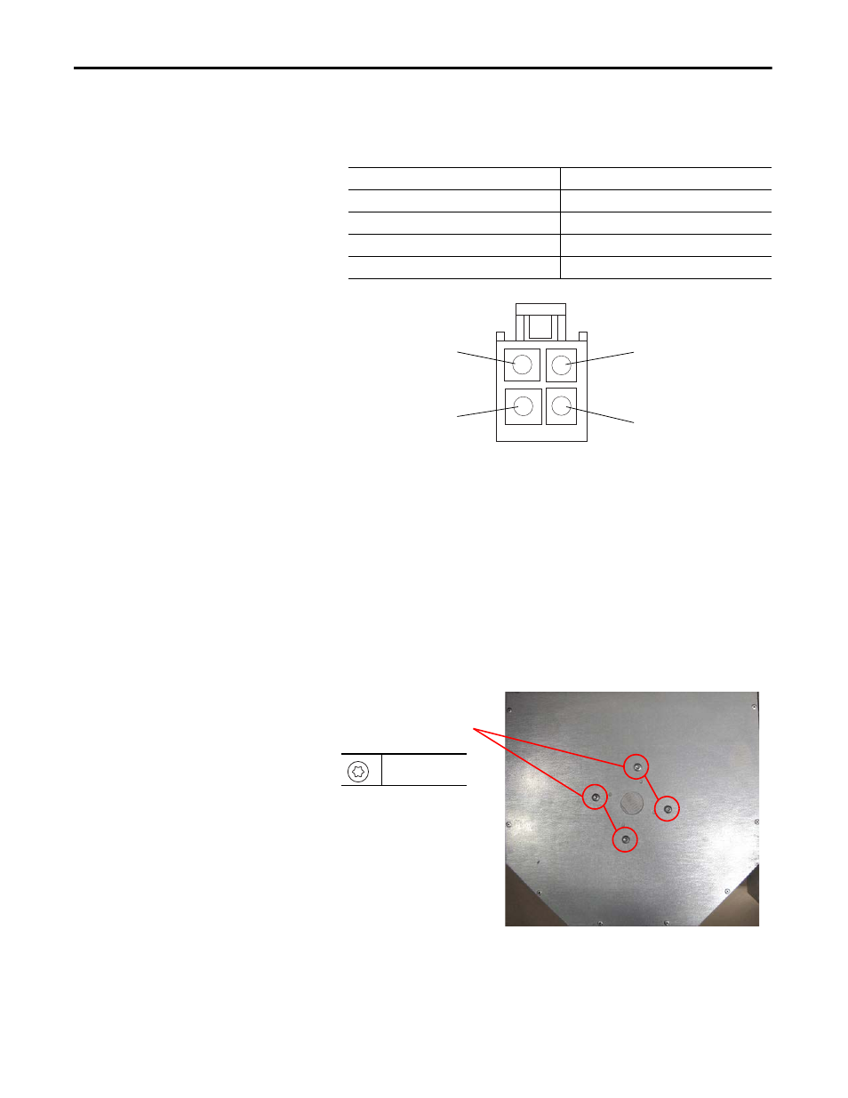
Measure the resistance between the fan supply wires.
DC Fan
: If the measurements are not similar to those in this table, replace
the DC fan.
7.
Remove the M5 x 16 mm hexalobular screw that secures the fan power
cable to the fan housing.
8.
Remove the grommets from the holes in the sheet metal.
9.
Remove the four screws that secure the fan to the sheet metal housing and
remove the fan. Retain the sheet metal housing for reuse.
Note: The Main AC and DC fans have different mounting hardware and
hole dimensions. The AC fan uses four M4 x 8 mm screws that are spaced
40 mm apart on the housing. The DC fan uses four M5 x 10 mm screws
that are spaced 65 mm apart on the housing. Based on the manufacturing
date, the sheet metal housing was fabricated for either an AC fan, a DC
fan, or both.
10.
Install the new main DC fan in reverse order. Verify that the fan turns
easily and does not make contact with the sheet metal housing or fan cable
before installing the fan assembly in the AFE.
Connection wires
Resistance ±5%
Red-Blue
∞ Ω
Red-White
∞ Ω
White-Yellow
∞ Ω
Blue-White
∞ Ω
White (Tach Output) Pin 3
Red (+) Pin 1
Blue (-) Pin 4
Yellow (Control Output) Pin 2
DC Fan Pinouts
8
T25
3.5 N
•
m (31.0 lb
•
in)
Image for SK-Y1-DCPS2-F13