Stabil-trak™ system and boom interlock system, Pressure suction return load sense – SkyTrak 8042 Service Manual User Manual
Page 883
Stabil-TRAK™ System and Boom Interlock System
10.42
Model 8042, 10042, 10054 Legacy
Rev. 10/03
10.12.7
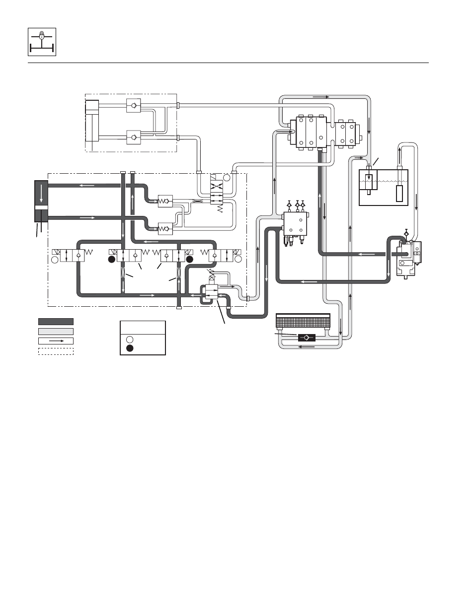
Hydraulic Circuit Operation - SLOW PIVOT Mode, Rod Oil Out
Conditions:
• Boom angle is above 40°
• Park brake OFF
• Service brake DISENGAGED
• Travel select lever in (F) FORWARD or (R)
REVERSE position
Operation:
As the boom is raised above 40°, the boom proximity
switch is deactivated, causing solenoids 12A and 12B to
de-energize and solenoids 4A and 4B to energize. This
allows oil to flow from the rod end of the Stabil-TRAK™
cylinder (1), through solenoid-operated valve 4B (2),
through a .060" orifice (3), through another .060" orifice (4),
then through solenoid-operated valve 4A (5), then to the
base end of the Stabil-TRAK™ cylinder.
The .060" orifices (3 and 4) in solenoid-operated valves
4A (5) and 4B (2) will slow the movement of the rear axle
in reaction to terrain changes. The frame sway will react
normally in this mode.
Because of the greater volume of oil required, extra oil is
required from the system through the 100 psi (7 bar)
reducing cartridge (6) in the Stabil-TRAK™ manifold. The
restrictions produce the slow movement, or SLOW PIVOT
mode.
STABIL-TRAK
CYLINDER
TM
HYDRAULIC
OIL COOLER
BYPASS
CHECK
VALVE
BYPASS
CHECK
VALVE
FTR
P
T
V
Pressure
Suction
Return
Load Sense
G3
G2
G1
4A
4B
12B
3
2B
2A
12A
FRAME
SWAY
CYLINDER
.060 DIA.
.030 DIA.
.060 DIA.
100 PSI
SOLENOID COIL
STATE
ENERGIZED
DE-ENERGIZED
DE
E
DE
E
E
DE
DE
P
T
C
PS
PB
PLT
PSG
PBG
G
IN T
T
AT
TA
C
H
TIL
T
P
FRAME SWAY
EXT/
RET
LFT/
LW
R
AU
X
STABIL-TRAK
MANIFOLD
TM
HYDRAULIC
RESERVOIR
SECONDARY
FUNCTION
MANIFOLD
PUMP
MAIN CONTROL
VALVE
MH3071
1
2
3
4
5
6