4 effective ground connections, 5 wiring harnesses, 1 removal and replacement – SkyTrak 8042 Service Manual User Manual
Page 604: 2 disassembly, Effective ground connections, Wiring harnesses, Removal and replacement, Disassembly
9.13
Model 8042, 10042, 10054 Legacy
Rev. 10/03
Electrical System
9.4
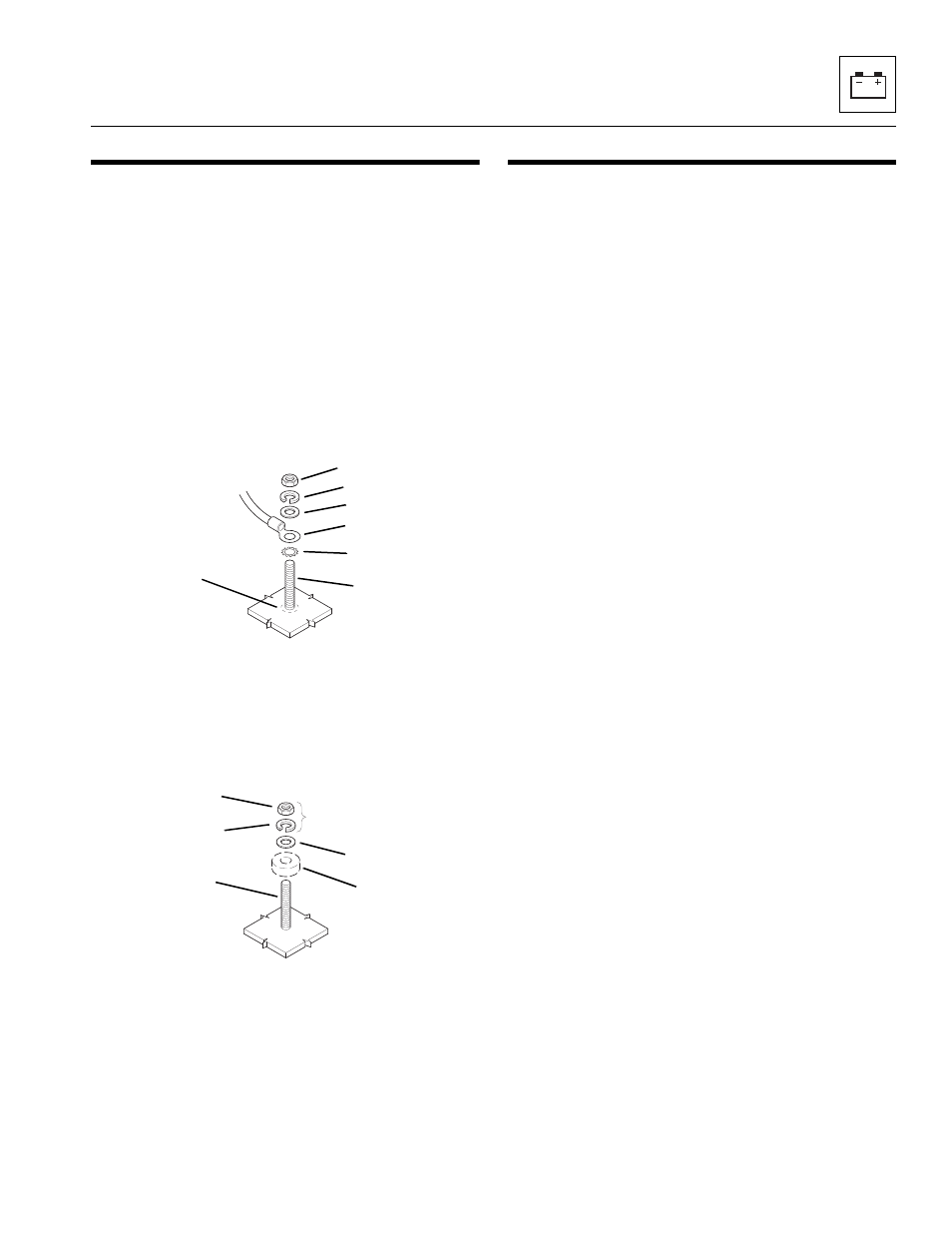
EFFECTIVE GROUND CONNECTIONS
1. Effective ground connections are essential to the
efficient operation of electrical components. If an
inadequate ground is suspected or determined,
establishing another ground may be desired. Also, in
the event a factory-authorized accessory is being
installed, it is necessary to follow the proper
sequence for providing an electrical ground. The
sequence for installing or attaching a component to
an electrical ground to a stud, bolt or capscrew (4) is
to provide a clean surface by eliminating paint and
rust from the area around the base of the stud (5).
Install a tooth type lockwasher (6), electrical wire
connector (7), flat washer (8), tooth or slot-type
lockwasher (9) and hex nut or locknut (10).
2. When an electrical component (11) is to be
grounded, eliminate paint and rust from around the
stud, bolt or capscrew (12), install a flat washer (13),
tooth type or slot-type lockwasher, or locking nut with
slotted type lockwasher (14) and hex nut or
locknut (15).
9.5
WIRING HARNESSES
For Serial Numbers 8042, 13198-18990,
10042, 13198-19030 & 10054 13189-19079; wiring on
the vehicle is contained within two separate wiring
harnesses, an engine harness and a cab harness.
For Serial Numbers 8042, 18991 - 19987,
10042 19031 - 19987, 10054, 19080 - 19987 And
8042/10042/10054, 0160002332 & After; wiring on the
vehicle is contained within three separate wiring
harnesses, an engine harness, ECM cab harness and a
cab harness.
A harness consists of black-nylon woven braiding,
providing a protective cover to bundle numerous wiring
groups, splices, terminals, connectors and (where
applicable) diodes. Each harness is identified with a part
number when the vehicle leaves the factory.
Each wire is identified by a wire number on each end of
the individual wire and by the color and gauge size of the
wire. The wire numbers are also identified on the
appropriate electrical schematic. All circuits have been
electrically tested for continuity, and all diodes have been
tested for correct biasing. Where several individual
connectors appear, the wiring leading to a particular
connector can help identify the specific circuit. For some
circuits, a colored band (tie wrap) is present, and is
affixed to the connector wiring and used as a color-code
indicator. If wiring needs to be replaced, use the correct
gauge size wiring. NEVER replace a wire with a smaller
gauge wire.
9.5.1
Removal and Replacement
Remove a wiring harness only if damaged or unusable.
Install a new harness one terminal at a time, as the old
harness is removed. Label or tag the terminal locations of
all wires, harness clips, tie wraps and conduit, as the old
harness is removed, to allow correct installation of the
new harness.
9.5.2
Disassembly
Disassembly of the wiring harness is not recommended
due to the precise arrangement of wires and splice
requirements. If it becomes necessary to replace wires,
use the correct gauge size wiring, and NEVER replace a
wire with a smaller gauge wire.
MA0871
4
5
6
7
8
9
10
MA0881
11
12
13
14
15