SkyTrak 8042 Service Manual User Manual
Page 824
9.233
Model 8042, 10042, 10054 Legacy
Rev. 10/03
Electrical System
2. Thoroughly clean the area around the upper and
lower valve body housing.
3. Remove screws securing the upper valve housing to
the transmission.
4. Remove upper valve body housing from transmission,
and set aside in a clean area, free of dirt, grease and oil.
5. Remove the upper valve housing flat gasket.
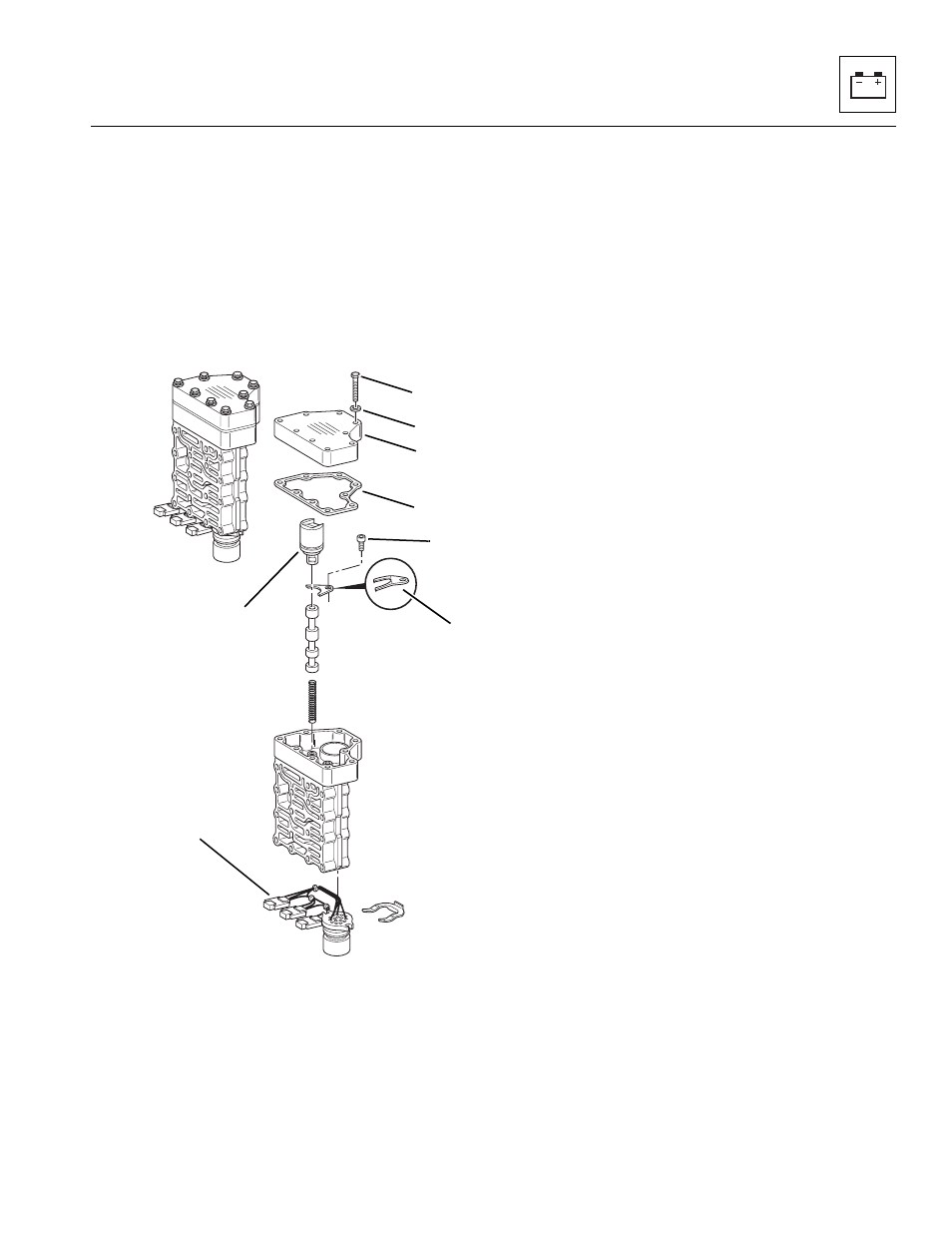
6. Remove the nine lower valve body protective cover
screws (17), lockwashers (18) protective cover (19)
and gasket (20)
7. Disconnect the internal wire connector (21) from the
solenoid valve that is being removed. Label the
internal wire connections if removing more than one
solenoid valve.
8. Remove the solenoid capscrew (22) and retaining
plate (23), securing the solenoid valve (24) to the
transmission.
9. Remove the solenoid valve (24) and replace.
f.
Transmission Lower Valve Body Solenoid
Installation
Note: When installing the solenoid valve into the valve
body, position the solenoid valve wires so they do not
interfere with the protective cover plate.
1. Install the solenoid valve (24) and retaining plate
(23). Connect the internal wire connector (21) to the
solenoid. Insure that the claw side of the retaining
plate (23) is facing down toward the valve body
surface.
2. Install the solenoid capscrew (22) and
torque to
53 lb-in (6 Nm).
3. Install the protective cover gasket (20 onto the valve
body. Position the protective cover (19) over the
gasket. Install lockwashers (18) and capscrews (17),
and tighten until the cover plate is compressed and it
sits flush over the gasket. Torque to 84 lb-in
(9,5 Nm).
4. Install the upper transmission valve body gasket and
upper valve body assembly to transmission.
5. Install the lockwashers and capscrews, and torque
screws to 84 lb-in (9,5 Nm).
6. If the vehicle has one battery, connect the
negative (-) battery cable to the negative (-) battery
terminal (15).
If the vehicle has dual batteries, connect both
negative battery cables to both negative (-) battery
terminals (16).
7. Test the operation of the transmission. Put the
transmission through its entire range of gears (speeds)
in both (F) FORWARD and (R) REVERSE, and
check that the transmission also shifts into
(N) NEUTRAL.
8. Verify that each function works properly and that the
transmission does not engage when in (N) NEUTRAL.
For further information, refer to the Transmission Service
Manual, Model ZF 4 WG-98 TC, P/N 8990455 (ZF P/N
5871 135 002).
MT2480
17
18
19
20
21
22
23
24