3 stabil-trak™ description, Stabil-trak™ description – SkyTrak 8042 Service Manual User Manual
Page 846
10.5
Model 8042, 10042, 10054 Legacy
Rev. 10/03
Stabil-TRAK™ System and Boom Interlock System
10.3
STABIL-TRAK™ DESCRIPTION
The patented rear axle lock or Stabil-TRAK™ system
works to stabilize the vehicle under various conditions.
The appropriate Owners/Operators manual contains
basic Stabil-TRAK™ information; a copy of the owners/
operators manual should always be available in the
storage compartment located on the left inside wall of the
cab, next to the seat support.
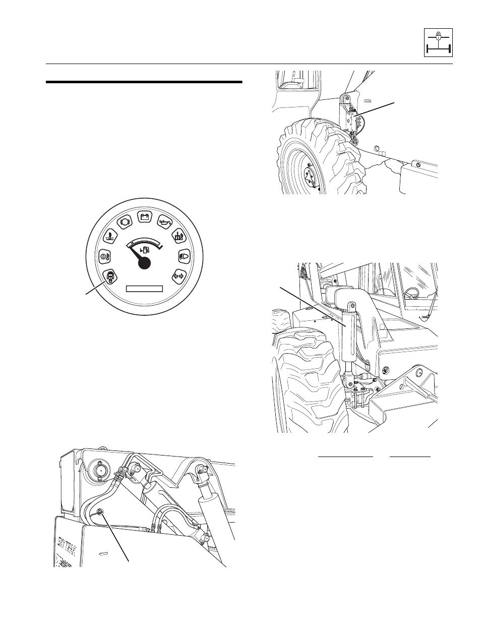
The operator’s instrument cluster Stabil-TRAK™ light (1)
goes ON when the Stabil-TRAK™ system is in the
LOCKED mode.
The stabilizing system operates via an interface between:
• boom proximity switch (2),
• park brake switch,
• service brake switch,
• gear selector in (N) NEUTRAL,
• hydraulic circuits,
• electrical circuits and
• five solenoid-operated valves on the Stabil-TRAK™
manifold (3)
The frame sway cylinder (4) is also involved in the Stabil-
TRAK™ system, but only passively, as hydraulic oil
travels between the frame sway cylinder and the Stabil-
TRAK™ manifold to accommodate Stabil-TRAK™
system operation.
The Stabil-TRAK™ lock system will be activated when
the boom angle is greater than 40° and one or more of the
following functions are activated:
• Engaging the Parking Brake Switch
• Placing the Travel Select Lever in (N) NEUTRAL
• Depressing and holding the Service Brake
• Model 10054 Only: Lowering both outriggers
onto solid terrain, and extending the boom
beyond a point between the “E” and “F” boom
extend letters (approximately 40' [12 m])
With the boom lowered to an angle of less than 40°, the
rear axle lock system is not active and none of these
functions will affect the Stabil-TRAK™ system.
0000 00
P
OH1810
1
MH2970
2
~
MH2980
3
MH2990
~
4