2 drive shaft maintenance, 3 drive shaft removal, Drive shaft maintenance – SkyTrak 8042 Service Manual User Manual
Page 291: Drive shaft removal, Section 5.4.3, “drive shaft removal.”)
Axles, Drive Shafts, Wheels and Tires
5.18
Model 8042, 10042, 10054 Legacy
Rev. 10/03
5.4.2
Drive Shaft Maintenance
Refer to the appropriate owners/operators manual for
information regarding the lubrication of the grease fittings
on the drive shafts.
5.4.3
Drive Shaft Removal
IMPORTANT: To help ensure optimum performance, the
drive shaft assemblies are specially balanced as a unit at
the factory. When servicing any flange yoke, slip yoke or
drive shaft tube, order a complete assembly if
components are bent or damaged. Refer to the appropriate
parts manual for ordering information.
Note: The drive shaft assemblies are balanced
assemblies. Mark the yoke and axle, transmission,
transfer case, and the shaft and slip yoke so that these
components can be returned to their original positions
when reinstalled. Yokes at both ends of the drive shaft
must be in the same plane to help prevent excessive
vibration.
a. Transmission-to-Axle Drive Shafts
1. Level the vehicle, ground the carriage, place the travel
select lever in the (N) NEUTRAL position, place the
neutral lock lever in the (N) NEUTRAL LOCK
position, engage the parking brake switch and shut
the engine OFF.
2. Place an Accident Prevention Tag on both the
ignition key switch and steering wheel, stating that
the vehicle should not be operated. (Refer to Section
1.5, “Accident Prevention Tags.”)
3. Unlock and open the right, left and rear engine
compartment access doors. Allow the engine,
transmission and hydraulic fluid to cool.
4. (SN 18990 (8042), 19030 (10042), 19079 (10054) &
Before Only) Disconnect the battery negative (-)
ground cable (1) at the battery negative (-) terminal
to prevent the engine from starting accidentally.
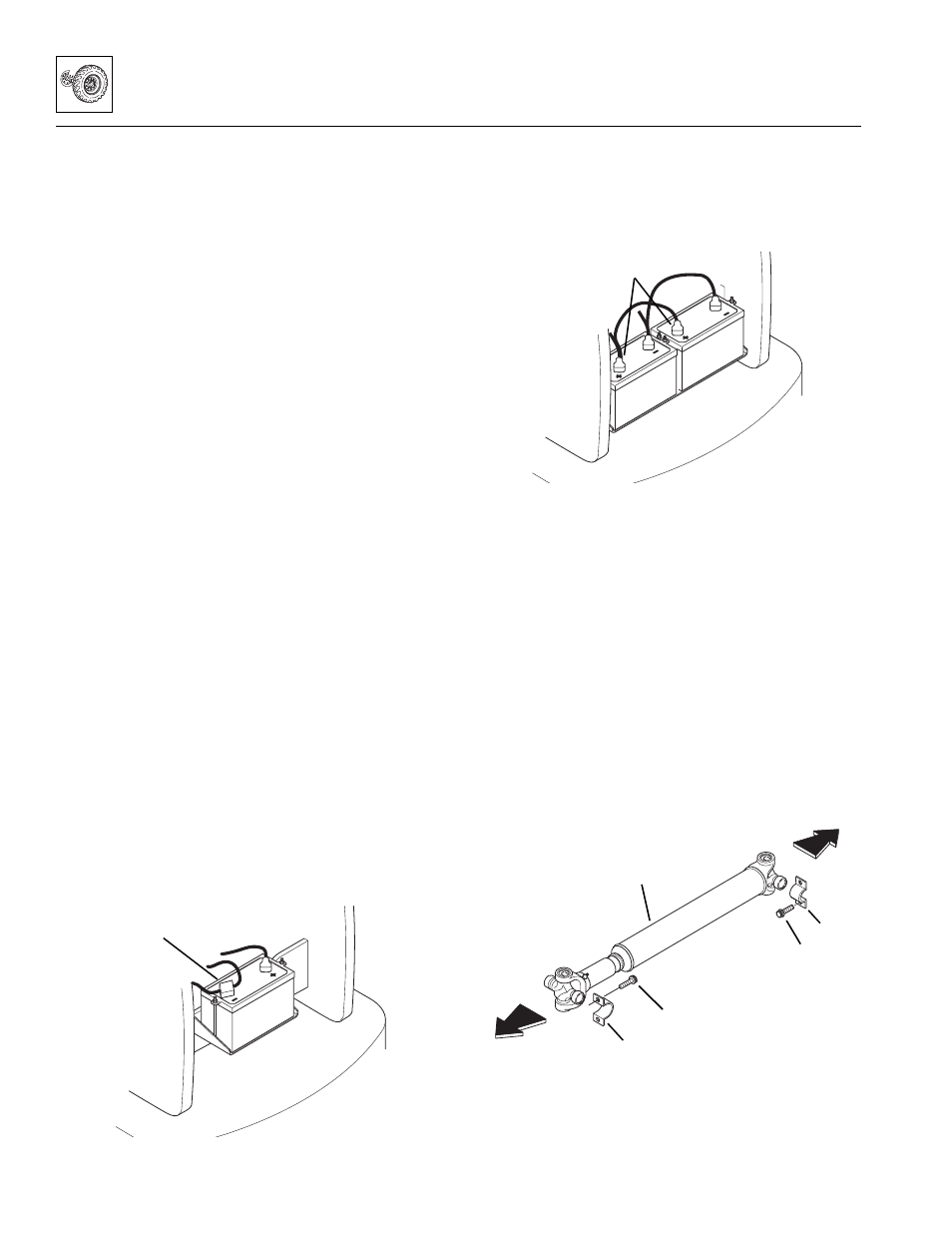
5. (SN 18991 (8042), 19031 (10042), 19080 (10054) &
After Only) Disconnect the battery negative (-)
ground cables (2) at the battery negative (-)
terminals to prevent the engine from starting
accidentally.
6. The drive shaft assembly is a balanced assembly.
Mark the yoke and axle, transmission and the shaft
and slip yoke so that these components can be
returned to their original positions when reinstalled.
Yokes at both ends of the drive shaft must be in the
same plane to help prevent excessive vibration.
7. Remove the four 12-point capscrews (3) and two
straps (4) securing the bearing cross to the
transmission output shaft flange.
8. Remove the four capscrews (5) and two straps (6)
securing the bearing crosses to the axle.
9. Remove the front drive shaft assembly (7).
10. Repeat Steps 6 thru 9 to remove the rear drive shaft.
OH2420
1
MH4440
2
MT0350
To
Axle
To Transmis-
sion
3
4
5
6
7