To section 9.14.7, b – SkyTrak 8042 Service Manual User Manual
Page 822
9.231
Model 8042, 10042, 10054 Legacy
Rev. 10/03
Electrical System
b. Upper and Lower Transmission Valve Body
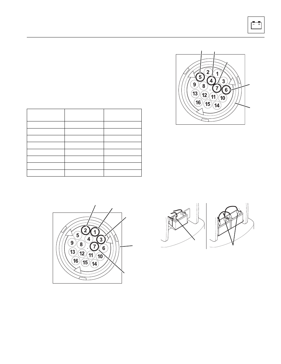
Solenoid Testing
Inspect the solenoid connector plugs (7 and 12).
Following the chart below, test each pin connection on
the upper transmission valve body connector for
continuity and shorting. Each solenoid should have
between 25.0 and 30.0 ohms of resistance when testing
with an ohm/volt meter. Replace a defective solenoid
valve. (Refer to Section 9.14.7, c. “Transmission Upper
Valve Body Solenoid Removal.”
Note: All six solenoids within both upper and lower
solenoid valve body housings are of the same design.
c. Transmission Upper Valve Body Solenoid
Removal
Note: Before removing the valve body protective cover,
clean the area around the housing to prevent
contamination.
1. If the vehicle has one battery, disconnect the
negative (-) battery cable at the negative (-) battery
terminal (17).
If the vehicle has dual batteries, disconnect both
negative battery cables from both negative (-) battery
terminals (18).
Solenoid Pin
Position
Active
Solenoid
Callout
1
Y1
2
Y2
3
Y3
7
Ground
4
Y4
5
Y5
6
Y6
7
Ground
MT1090
7
8
9
10
11
MT1100
12
13
14
15
16
MH4890
17
18