SkyTrak 8042 Service Manual User Manual
Page 127
Boom
3.66
Model 8042, 10042, 10054 Legacy
Rev. 03/04
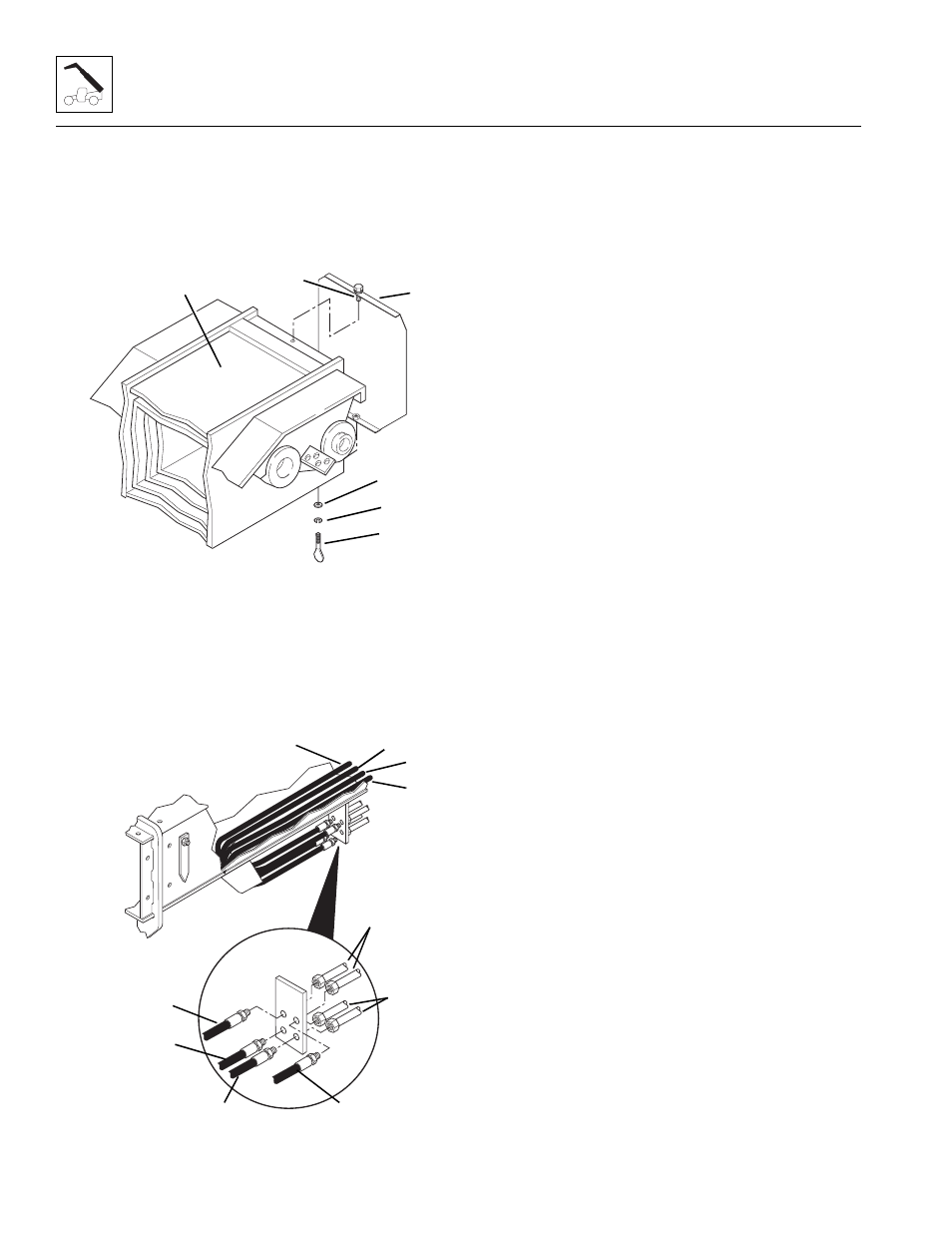
9. Remove the thumbscrew (1), lockwasher (2) and flat
washer (3) holding the rear cover (4) to the rear of
the outer boom (5). Lift the rear cover straight up
until the capscrew (6) in the top of the cover clears
the retaining hole in the top of the outer boom.
Remove the cover from the outer boom.
10. At the front of the outer boom, label and remove the
auxiliary hoses (7 and 8) from the bottom tube
assemblies (9) at the mounting plate. Cap the hose
ends.
11. Label and remove the Attachment Tilt hoses
(10 and 11) from the top tube assemblies (12) at the
mounting plate. Cap the hose ends.
12. Label and remove the four hoses from the hose reel.
The center bolt (13) can remain in place to hold the
hose reel and side plates together:
a. Remove the elastic locknut (14) and flat
washer (15) from the lower retaining shoulder
bolt (16). While pulling the shoulder bolt out,
catch the spacers (17) from between the plates
as the bolt is removed. Pull the bolt out far
enough to remove the hoses from the hose reel.
b. Pull the four hoses from the lower part of the
hose reel out from between the outer boom and
the primary intermediate boom sections.
Carefully lay the hoses out behind the back of the
boom.
c. After the hoses are removed from between the
outer and primary intermediate boom sections,
reinsert the shoulder bolt (16) through the plates,
inserting the spacers (17) between the plates as
the bolt is inserted. Reassemble the flat
washer (15) and elastic locknut (14) to hold the
shoulder bolt in place. DO NOT fully tighten at
this time.
d. Remove the elastic locknut (18) from the upper
retaining capscrew (19). While pulling the
capscrew out, catch the spacers (20) from
between the plates as the capscrew is removed.
Pull the capscrew out far enough to remove the
hoses from the hose reel.
e. After the hoses are removed, reinsert the
capscrew (19) through the plates, inserting the
spacers (20) between the plates as the capscrew
is inserted. Reassemble the elastic locknut (18)
to hold the capscrew in place. DO NOT fully
tighten.
MH5690
~
1
2
3
4
5
6
7
8
9
10
11
12
MH1450