5 outrigger switches (10042/10054 only), Section 9.14.5, Outrigger switches (10042 – SkyTrak 8042 Service Manual User Manual
Page 818: 10054 only), Outrigger switches (10042/10054 only)
9.227
Model 8042, 10042, 10054 Legacy
Rev. 10/03
Electrical System
9.14.5
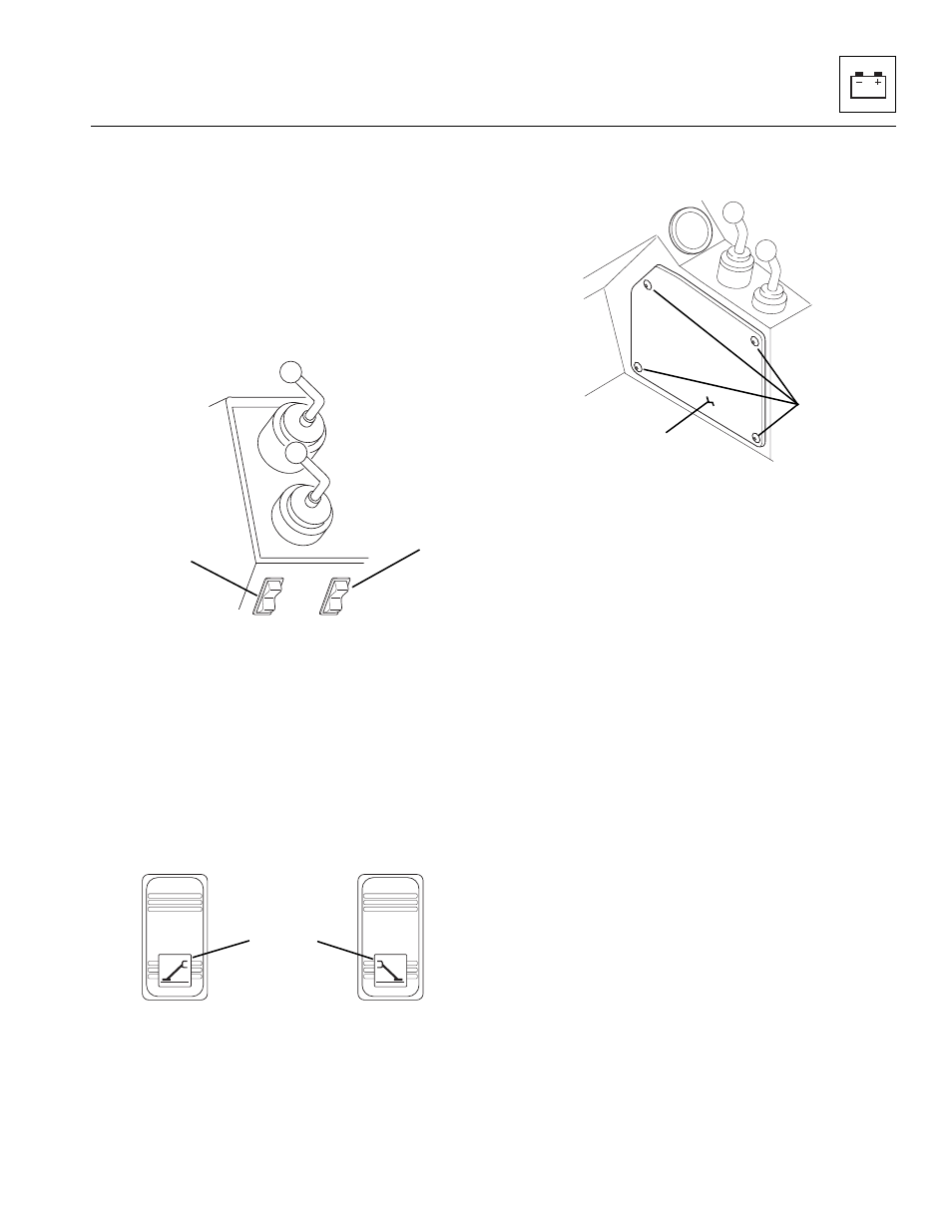
Outrigger Switches (10042/10054 Only)
Inspect the switch terminals for continuity and shorting in
both the non-depressed and depressed positions.
Replace a defective or faulty switch with a new switch.
a. Left and Right Outrigger Switches
The left and right outrigger switches (5 and 6) control the
RAISE and LOWER movements of both outriggers. The
rocker switches are spring-loaded to return to the center
(STOP) position when released.
Both outriggers are wired in series and have pressure
switches (10054 only) that detect a pressure difference
when one of the outriggers contacts the ground. Both
outriggers must make contact with the earth (10054 only)
before the boom will be allowed to fully extend.
b. Outrigger Switch Removal
Note: The LEFT and RIGHT outrigger switches function
the same but have the LEFT (7) or RIGHT (8) icon on
each switch. If removing both switches, ensure that you
install each switch in the proper bezel location.
1. If the vehicle has one battery, disconnect the
negative (-) battery cable at the negative (-) battery
terminal (1).
If the vehicle has dual batteries, disconnect both
negative battery cables from both negative (-) battery
terminals (2).
2. Remove the four fasteners (9) securing the right side
access panel (10), and remove the panel.
3. Carefully pry the outrigger switch (5 or 6) and wiring
out of the mounting hole.
4. Label and disconnect the wiring from the outrigger
switch. Remove the switch from the vehicle.
c. Outrigger Switch Disassembly
DO NOT disassemble the outrigger switch. Replace a
defective or faulty switch with a new switch.
d. Outrigger Switch Inspection
Inspect the switch terminals for continuity and shorting in
both the RAISE and LOWER positions. Replace a
defective or faulty switch with a new switch.
e. Outrigger Switch Installation and Testing
1. Route the wiring connectors through the bezel, then
connect the wiring to the outrigger switch (5 or 6) as
labeled during switch removal.
2. Properly position the symbol (7 and 8) on the switch
to the bottom, then press or “snap” the switch into
place in the bezel.
3. Install the right side access panel (10), four fasteners
(9) and tighten.
4. If the vehicle has one battery, connect the
negative (-) battery cable to the negative (-) battery
terminal (1).
If the vehicle has dual batteries, connect both
negative battery cables to both negative (-) battery
terminals (2).
5. Clear the area around the vehicle of personnel and
any obstructions to vehicle travel.
6. Start the vehicle, and lower or raise effected
outrigger through full travel.
OH1700
5
6
MH3920
MH3930
7
8
OH2430
9
10