Ep 4. if – SkyTrak 8042 Service Manual User Manual
Page 83
Boom
3.22
Model 8042, 10042, 10054 Legacy
Rev. 03/04
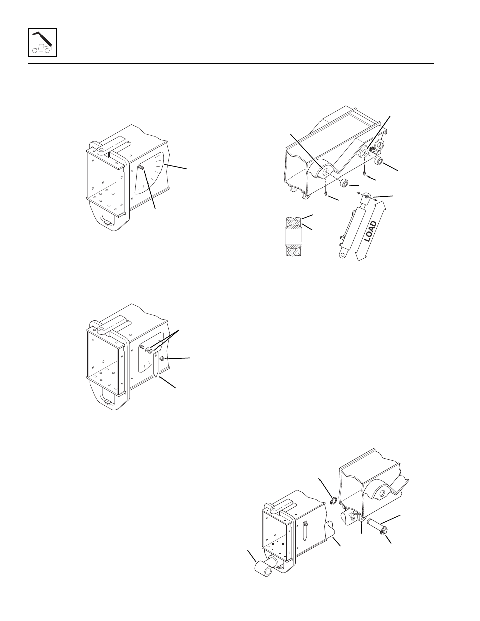
4. Assemble a new angle indicator decal (1) to the left
side of the boom assembly. Place the hole in the
decal around the weld stud (2) and line up the upper
edge of the decal parallel with the top edge of the
boom assembly.
5. Place the two flat washers (3) and the angle
indicator (4) onto the weld stud. Secure in place with
the locknut (5). After tightening the locknut, the angle
indicator must pivot freely on the weld stud. If the
angle indicator binds, loosen the locknut slightly.
Recheck to be sure the angle indicator pivots freely.
6. Install new or saved Lift/Lower cylinder bearings (6)
into the Lift/Lower cylinder mounts (7) on each side
of the boom assembly. Orient the fracture (8) in the
outer race of each bearing so that it is perpendicular
to the force of the load. Press the bearings into
position until the edge of the outer race (9) of each
bearing is flush with the edge of the plate (10).
7. Install new or saved Slave cylinder bearings (11) into
the Slave cylinder mounts (12) on each side of the
boom assembly. Orient the fracture (8) in the outer
race of each bearing so that it is perpendicular to the
force of the load. Press the bearings into position
until the edge of the outer race (9) of each bearing is
flush with the edge of the plate (10).
8. Install grease fittings (13) into the Lift/Lower cylinder
mounts (7) and the Slave cylinder mounts (12) on
the outer boom. Tighten all the grease fittings.
Note: Slings and a hoist are required to perform the
following step.
9. Position the Extend/Retract cylinder (14) with the
extend and retract port elbows facing down. Place
the rod end of the Extend/Retract cylinder (15)
through the Extend/Retract cylinder retainer at the
front of the outer boom. At the rear of the Extend/
Retract cylinder, align the hole in the base end of the
cylinder with the holes in the mounting ears (16)
under the outer boom.
10. Coat the base end cylinder pin with anti-seize
compound. Insert the base end cylinder pin (17)
through both mounting ears and the base end of the
Extend/Retract cylinder. Secure the pin in place with
a retaining ring (18) on each side of the pin. Be sure
the retaining rings are completely seated in the
grooves on each side of the pin.
MH1320
1
2
MH1300
3
4
5
MH4380
6
7
8
9
10
11
12
13
MH1350
14
15
16
17
18