25 attachment tilt and slave circuit description, 26 pump and cooling circuit description, 27 auxiliary hydraulics circuit description – SkyTrak 8042 Service Manual User Manual
Page 477: Attachment tilt and slave circuit description, Pump and cooling circuit description, Auxiliary hydraulics circuit description
Hydraulic System
8.62
Model 8042, 10042, 10054 Legacy
Rev. 10/03
8.8.25
Attachment Tilt and Slave Circuit
Description
System pressure is applied in the attachment tilt and
slave cylinder circuit from the attachment tilt section of
the main control valve.
Fluid flow is directed to either side of the attachment tilt
and slave cylinder pistons by shifting of the spool valve in
the attachment tilt section of the main control valve
assembly. The spool valve is shifted by the operator
joystick and its associated control cable.
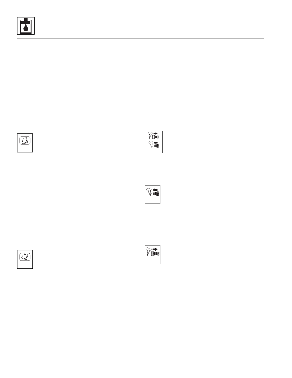
Moving the joystick BACKWARD controls attachment tilt
UP. Moving the joystick FORWARD controls attachment
tilt DOWN.
a. DOWN Position (refer to page 8.32)
With the joystick moved FORWARD, the
attachment tilts DOWN. The spool valve in the
main control valve is shifted so system pressure
is directed to the rod end of the attachment tilt
cylinder and the slave cylinders.
The extension of the slave cylinders is fixed by the
position of the boom, so that only the attachment tilt
cylinder is retracted to tilt the attachment downward. The
pilot pressure opens the counterbalance valve. The open
counterbalance valve allows return oil from the base of
the attachment tilt cylinder to flow to ports of the
attachment tilt section of the main control valve, to the oil
cooler, to the return filter and then to the reservoir.
If system pressure reaches 3250 ±100 psi (224 ±7 bar)
the main relief will open and allow hydraulic oil to return
to the return filter and to the reservoir. In any case, if the
return filter becomes restricted, hydraulic oil will bypass
the filter when the pressure reaches 25 psi (1,7 bar).
b. UP Position (refer to page 8.34)
With the joystick moved BACKWARD, the
attachment tilts UP. The spool valve in the main
control valve is shifted so system pressure is
directed to the base end of the attachment tilt
cylinder and the slave cylinders.
If system pressure reaches 3250 ±100 psi (224 ±7 bar)
the main relief will open, allowing hydraulic oil to flow to
the return filter and to the reservoir. If the return filter
becomes restricted, hydraulic oil will bypass the filter
when the pressure reaches 25 psi (1,7 bar).
Return oil from the rod side of the attachment tilt cylinder
is directed back to the attachment tilt section of the main
control valve through the spool valve, to the oil cooler, to
the return filter and then to the reservoir.
If the return filter becomes restricted, hydraulic oil will
bypass the filter when the pressure reaches 25 psi
(1,7 bar).
8.8.26
Pump and Cooling Circuit Description
In the pump and cooling circuit, the pump draws fluid from
the hydraulic reservoir, and sends pressurized fluid to the
main control valve.
The main control valve regulates maximum system
operating pressure for various vehicle functions. The
piston pump sends fluid to the main control valve and to
the secondary function manifold. When fluid from the
main control valve is returned to the reservoir, it is sent
through the hydraulic oil cooler first. There is a return line
from the main control valve to the tank that will bypass the
cooler when pressure reaches the 65 psi (4.5 bar).
8.8.27
Auxiliary Hydraulics Circuit Description
The auxiliary hydraulics circuit functions can be
achieved by moving the auxiliary attachment
control lever. Moving the control lever to the left
controls auxiliary function in one direction,
usually forward, if the auxiliary device is so
designed. Moving the control lever to the right controls
auxiliary functions in reverse, or the opposite direction.
a. Male Coupler Pressurized (refer to page 8.38)
With the auxiliary attachment control lever moved
to the right, pressure will shift the auxiliary spool
valve, allowing system pressure to flow from the
auxiliary spool valve to the male connection of the
auxiliary hydraulics coupler. From the coupler, fluid flows
to the attachment, back to the female auxiliary coupler, to
the auxiliary spool valve, to the oil cooler, to the return
filter and then to the reservoir.
b. Female Coupler Pressurized (refer to page 8.40)
With the auxiliary attachment control lever
moved to the left, pressure will shift the auxiliary
spool valve, allowing oil to flow from the auxiliary
spool valve to the female connection of the
auxiliary hydraulic coupler. From the coupler, fluid flows
to the attachment, back to the male auxiliary coupler, to
the auxiliary spool valve, to the oil cooler, to the return
filter and then to the reservoir.
MT3780
MT3790
MA7250
MA7260
MA7270