11 hydraulic system pump, 1 pump failure analysis, 2 pump replacement – SkyTrak 8042 Service Manual User Manual
Page 485: Hydraulic system pump, Section 8.11.2, A. “pump removal, Pump failure analysis, Pump replacement, Warning
Hydraulic System
8.70
Model 8042, 10042, 10054 Legacy
Rev. 10/03
8.11
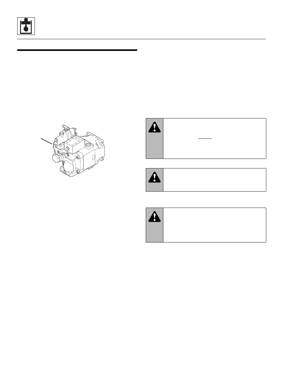
HYDRAULIC SYSTEM PUMP
The piston pump (1) is attached to the transmission. The
rotation of the pump shaft causes the cylinder block, shoe
plate and pistons to rotate. The angle of the yoke face
creates a reciprocating motion to each piston within the
cylinder block. As the pistons move out of the cylinder
block, a vacuum is created and fluid is forced into the void
through a 2" inside diameter hose by atmospheric
pressure. The motion of the piston reverses, and fluid is
pushed out of the cylinder block into the outlet port
through a 3/4" inside diameter hose to the secondary
function manifold.
Hydraulic system pressure begins at the pump. Various
factors are involved in creating the relatively high
pressure used in the hydraulic system. Pump rpm,
controlled via a transmission input shaft (and dependent
on engine rpm), the internal pump passageways and the
differential between pump inlet (2" I.D.) and outlet
(3/4" I.D.) openings, all contribute to pressure supplied.
8.11.1
Pump Failure Analysis
The pump is the “heart” of the hydraulic system, and
whenever there is a problem in the system, the pump
often is blamed. However, pump failure is seldom due to
failure of pump components. Pump failure usually
indicates another problem in the hydraulic system.
According to pump manufacturer statistics, 90-95 percent
of pump failures are due to one or more of the following
causes:
• Aeration
• Cavitation
• Contamination
• Excessive Heat
• Over-Pressurization
• Improper Fluid
In the event of pump failure, investigate further to
determine the cause of the problem.
8.11.2
Pump Replacement
a. Pump Removal
1. Park the vehicle on a firm, level surface, fully retract
the boom, raise the boom, place the travel select lever
in (N) NEUTRAL, place the neutral lock lever in the
(N) NEUTRAL LOCK position, engage the park brake
switch and shut the engine OFF.
2. Place an Accident Prevention Tag on both the
ignition key switch and the steering wheel, stating
that the vehicle should not be operated. Refer to
Section 1.5, “Accident Prevention Tags.”
3. Temporarily block up or support the raised boom.
4. Unlock and open the rear door. Allow the hydraulic
fluid to cool.
5. Drain the hydraulic oil reservoir. Refer to the
appropriate Legacy Owners/Operators Manual,
Hydraulic Oil and Filter Change.
6. Remove the transmission covers.
7. Thoroughly clean the pump and surrounding area,
including all hoses and fittings before proceeding.
Note: Cap all hoses as you remove them to prevent
unnecessary fluid spillage.
8. Remove the four capscrews (2) and four
lockwashers (3) securing the flange halves (4) to the
pump (5). Remove the inlet hose (6) and o-ring (7).
Note: It is not necessary to remove the T-bolt band
clamp (8) and inlet hose (6) from the hydraulic reservoir
outlet connection.
MH3310
1
WARNING:
DO NOT get under a raised
boom unless the boom is blocked up. Always
block the boom before doing any servicing that
requires the boom to be up. Unexpected
lowering of the boom may cause death or
serious injury.
WARNING:
Hot hydraulic fluid can
cause severe burns. Wait for hydraulic fluid to
cool before servicing any hydraulic component.
WARNING:
Escaping hydraulic fluid
under pressure can penetrate the skin, causing
death or serious injury. Relieve hydraulic
pressure before servicing any hydraulic
component.