SkyTrak 8042 Service Manual User Manual
Page 69
Boom
3.8
Model 8042, 10042, 10054 Legacy
Rev. 03/04
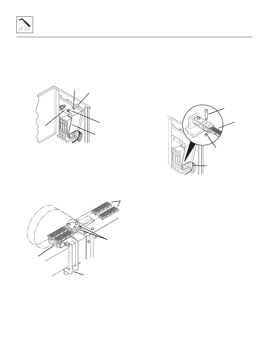
17. At the rear of the boom, measure the amount of
threads protruding beyond each elastic locknut (1)
and record that measurement for reassembly.
Remove the two elastic locknuts (1) and flat
washers (2) holding both extend chain clevis’ (3) to
the anchor plate (4) on the inner boom (5). Save the
flat washers and discard the elastic locknuts.
18. At the front of the intermediate boom (6), pull both
extend chains (7) out from between the inner and
intermediate boom sections. The extend chains can
remain anchored between the yoke plates (8) on the
outer boom. Loop both chains over the top of the
chain sheave (9) and lay the chains on top of the
outer boom.
Note: Record the location of the shoulder bolt (10) to
ensure correct installation.
19. At the rear of the boom, locate the retract chain (11)
on the right side of the boom. In front of the retract
chain sheave, locate the shoulder bolt (10) which
holds the retract chain to the anchor plates on the
inner boom. Remove the elastic locknut (12) from
the shoulder bolt and remove the shoulder bolt. Save
the shoulder bolt and discard the elastic locknut. Allow
the retract chain to hang out the rear of the boom.
Note: If replacing the inner boom assembly with a new
inner boom, the quick attach assembly and the Attachment
Tilt cylinder should be removed at this time.
If the inner boom is not to be replaced, the quick attach
assembly and Attachment Tilt cylinder can remain in
place. Proceed to Step 29.
20. Remove the elastic locknut (13) and capscrew (14)
holding the Attachment Tilt cylinder rod end pin (15)
to the quick attach assembly (16). Save the
capscrew and discard the elastic locknut.
21. Support the rod end of the Attachment Tilt
cylinder (17). Use a brass punch and a rawhide
hammer to remove the rod end pin (15) from the
quick attach assembly.
22. Inspect the pin (15) for nicks or surface corrosion.
Use fine emery cloth to fix minor nicks or corrosion.
If damaged and if it cannot be repaired, the pin must
be replaced.
MH0911
1
2
3
4
5
MH0920
6
7
8
9
MH2550
10
11
12