SkyTrak 8042 Service Manual User Manual
Page 541
Hydraulic System
8.126
Model 8042, 10042, 10054 Legacy
Rev. 10/03
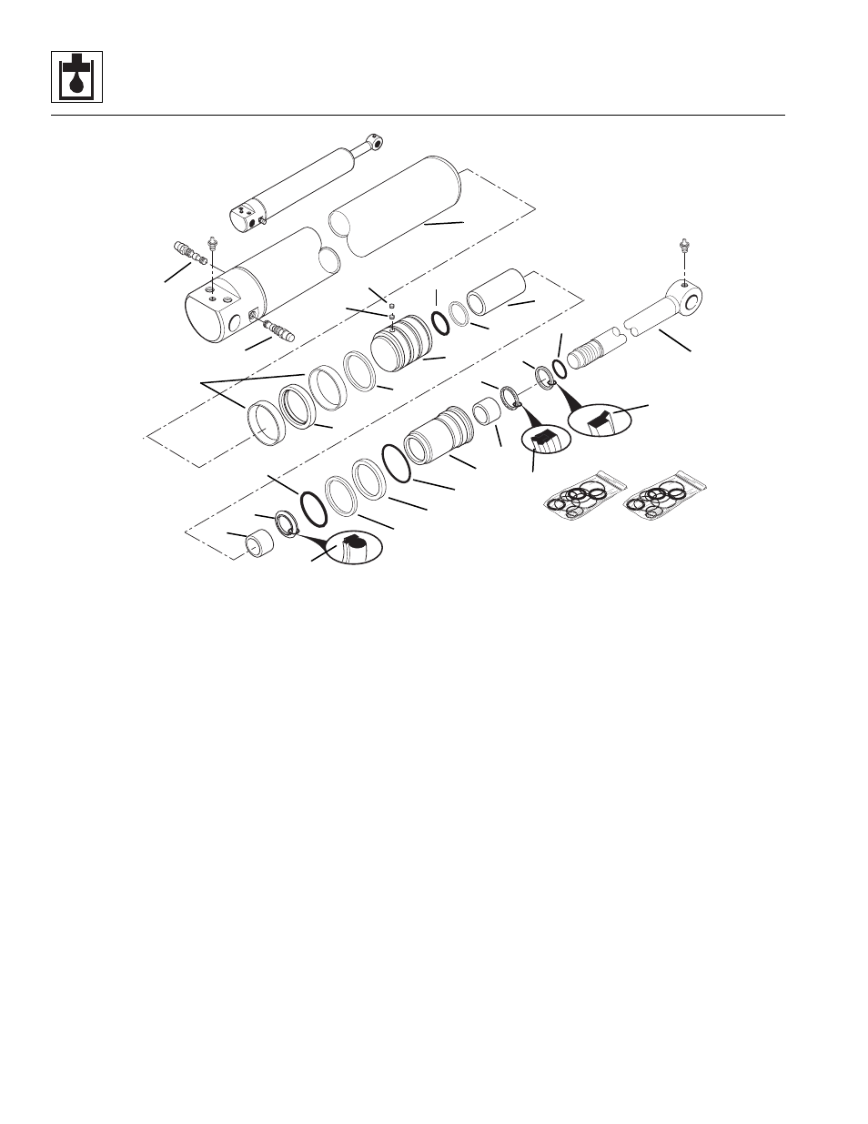
e. Extend/Retract Cylinder Assembly
Note: Follow Section 8.13.3, “General Cylinder
Assembly Instructions.”
1. Install a new small oiled o-ring (1) and new back-up
2. Install the square ring (4), the piston seal (5) and
both precision wearbands (6) onto the piston (3).
3. Install the precision wearbands (7) and the buffer
seal (8), if used, into the front end of the head gland
(9). Orient the buffer seal as shown (10).
4. Install the o-ring (11) and the U-cup seal (12)
orienting the edge (13).
5. Install the sealed outside diameter heavy-duty rod
wiper (14). The wiper lip (15) should be toward the
outer end of the head gland (9) and the seal lips
toward the inner end of the head gland. Use tools
that will not damage the seals.
6. Install a new oiled o-ring (16), locking insert (17),
back-up ring (18) and oiled o-ring (19) onto the head
gland (9).
7. Secure the rod (20) in a soft-jawed vise, and put a
padded support below and near the threaded end of
the rod to help prevent damage to the rod.
8. Carefully slide the head gland (9), then the rod
spacer (21) onto the rod (20).
9. Carefully slide the piston (3) onto the rod (20). Apply
Loctite Threadlocker #271 to the piston and torque
the piston to 1800-2000 lb-ft (2440-2712 Nm).
10. Apply Loctite Threadlocker #243 to the setscrew
threads. Thread the first setscrew (22) and then the
second (23) into the piston (3). Torque the setscrews
to 155-165 lb-in (18-19 Nm).
IMPORTANT: Avoid using excess force when clamping
the cylinder in a vise. Apply only enough force to hold the
cylinder securely. Excessive force can damage the
cylinder.
11. Secure the extend/retract cylinder tube (24) in a soft-
jawed vise or other acceptable holding equipment if
possible.
12. Lubricate the inside of the tube (24) and outside of
the piston (3) and head gland (9) with clean, filtered
hydraulic oil.
13. Apply a compression sleeve or other suitable tool to
the head gland (9) and piston (3) in order to
compress the o-rings, back-up rings and seals, while
inserting the assembled piston, rod and head gland
into the tube (24).
MH2880
1
2
3
4
5
6
7
8
9
10
11
12
13
14
15
16
17
18
19
20
21
22
23
24
25
26