3 instrument cluster, Instrument cluster, Caution – SkyTrak 8042 Service Manual User Manual
Page 801
Electrical System
9.210
Model 8042, 10042, 10054 Legacy
Rev. 10/03
b. Disassembly
DO NOT disassemble the back-up alarm. Replace a
defective or faulty alarm with a new part.
c. Inspection and Replacement
Inspect the wiring harness connector and alarm terminals
for continuity and shorting. Replace a defective or faulty
alarm with a new part.
d. Installation and Testing
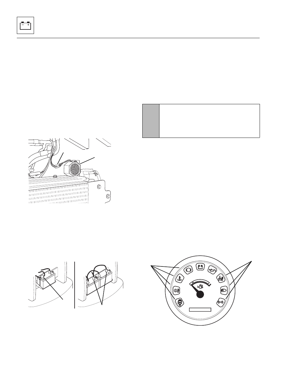
1. Position the back-up alarm (1) onto the 1/4-20 studs
located on the inside frame wall at the rear of the
vehicle. Secure with two lockwashers and 1/4-20
nuts.
2. Connect the wiring harness connector lead (2) to the
back-up alarm.
3. If the vehicle has one battery, connect the
negative (-) battery cable to the negative (-) battery
terminal (3).
If the vehicle has dual batteries, connect both
negative battery cables to both negative (-) battery
terminals (4).
4. Test the alarm by turning the ignition key switch to
the RUN position and shifting the travel select lever
into the REVERSE position. The back-up alarm
should sound.
9.11.3
Instrument Cluster
The information under this heading deals mainly with the
description and function of each indicator in the
operator’s instrument cluster. Appropriate service
procedures for each circuit, as applicable, appear
elsewhere in this section of the manual.
The instrument cluster is of solid-state, printed circuit
design, and contains one
wiring terminal and a display
panel that provides overall monitoring of vehicle functions
and status.
Prevent the instrument cluster from coming into contact
with static or other electrical sources. When washing the
vehicle, keep spray away from the operator’s display
panel. Replace a defective, malfunctioning or faulty panel
with a new unit.
The operator’s display panel provides important
information in a “user friendly” design with easily
recognizable graphic and alpha-numeric indicators. The
panel provides information the operator needs to know
about vehicle and engine functions.
When testing circuits connected to the instrument cluster,
disconnect the harness connector and test the harness
side only.
a. Power-Up Lights
When the ignition key switch is turned to power up the
vehicle, all lights in the instrument cluster (5 and 6) will
illuminate for three seconds as a test function.
MH29402
1
2
MH4890
3
4
CAUTION:
Before performing ANY
welding on vehicle, disconnect the negative (-)
battery cable at the negative (-) battery terminal.
Failure to remove the negative (-) battery cable
will result in damage to vehicle electronic systems.
0000 00
P
OH1810
5
6