Auxiliary hydraulic joystick assembly replacement – SkyTrak 8042 Service Manual User Manual
Page 256
4.17
Model 8042, 10042, 10054 Legacy
Rev. 10/03
Cab and Covers
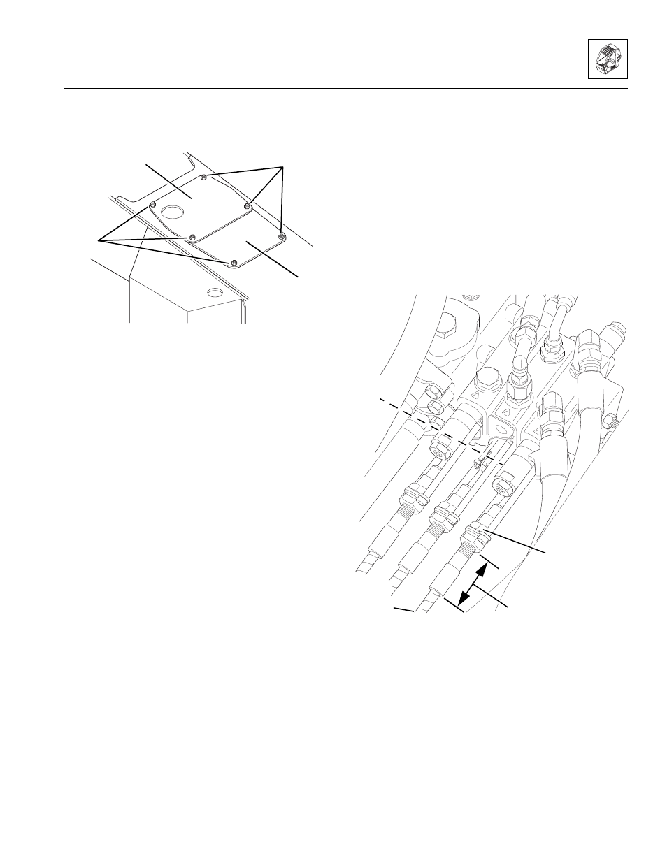
12. Install the upper (11) and lower (10) transmission
covers; secure using six hex nuts, six lockwashers
and six flat washers (12).
4.3.7
Auxiliary Hydraulic Joystick Assembly
Replacement
a. Auxiliary Hydraulic Joystick Removal
1. Park the vehicle on a firm, level surface. Allow
sufficient overhead and side clearance for cab
removal. Level the vehicle, ground the attachment,
place the travel select lever in the (N) NEUTRAL
position, place the neutral lock lever in the (N)
NEUTRAL LOCK position, engage the parking brake
switch and shut the engine OFF.
2. Place an Accident Prevention Tag on both the
ignition key switch and steering wheel, stating that
the vehicle should not be operated. (Refer to Section
1.5, “Accident Prevention Tags.”)
3. Unlock and open the rear door. Allow the engine and
hydraulic fluid to cool.
4. Disconnect the battery negative (-) cable or cables at
the battery negative (-) terminal.
5. Remove six hex nuts, six lockwashers and six flat
washers (12) securing the upper (11) and lower (10)
transmission covers to the frame. Remove the
covers.
Note: Record the distance (13) from the outer jam nut to
the end of the ferrule on cable, to ensure correct
adjustment when reinstalling cable.
6. Disconnect the boom auxiliary hydraulic control
cable:
a. Remove the spring pin (14) and anchor pin. Save
the spring pin and anchor pin for installation.
b. Loosen and remove the inner jam nut (15), and
remove the auxiliary hydraulic control cable (16)
from the bracket. Save the jam nut for
installation.
c. Route the cable through the opening at the
bottom of the frame.
7. Remove four button-head capscrews (8) and remove
the console panel (9).
MA8620
~
~
10
11
12
MA8490
~
13
14
15
16