7a.12.3 coupler and drive shaft installation, 7a.12.3, Coupler and drive shaft installation a.40 – SkyTrak 8042 Service Manual User Manual
Page 363
Engine: Cummins 4BT3.9 and 4BTA3.9
7A.40
Model 8042, 10042, 10054 Legacy
Rev. 10/03
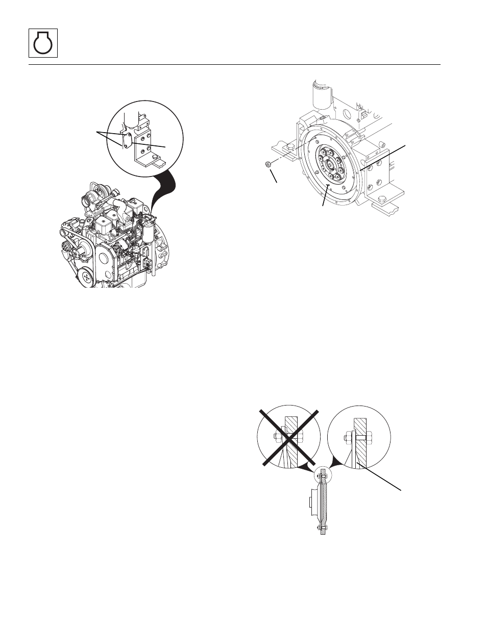
4. Remove the capscrews (1) securing the small
access cover (2).
5. Remove the capscrews and locknuts (3) securing
the coupler (4) to the flywheel. Turn the engine by
hand, using the fan belt, until the capscrews line up
with the access hole (2).
6. At this time, use a suitable cleaner/solvent and
thoroughly clean the mounting lip of the flywheel.
Wipe any debris from the inside of the bell housing.
Use the cleaner to clean the threaded holes (5)
around the flange of the bell housing.
7A.12.3
Coupler and Drive Shaft Installation
1. Use cleaner to clean the backside of the coupler,
where it comes in contact with the flywheel.
Note: The new coupler weighs approximately
56 lbs (25,4 kg) and requires two people, one on each
side, to install.
Note: ALWAYS replace elastic locknuts with new elastic
locknuts to help ensure proper fastening.
2. Place the new coupler (4) into the indentation of the
flywheel and use new Grade 8 capscrews and
locknuts (3) to secure the coupler to the flywheel.
3. Insert one capscrew into the access hole (2) on the
rear right side of the bell housing and through the
flywheel and coupler. Assemble a new elastic
locknut onto the capscrew. DO NOT fully tighten at
this time.
4. Turn the flywheel 180° and insert another capscrew
and assemble with another new elastic locknut.
DO NOT fully tighten until all of the capscrews and
locknuts are in place.
5. After all the capscrews are in place, check to be sure
the coupler is resting squarely in the indentation of
the flywheel (6). Torque all the capscrews to 37 lb-ft
(48 Nm).
6. Install the small access cover plate (2), to the right
side of the engine and tighten the hardware securely.
SH3060
1
2
SH3070
3
4
5
SH1100
6