6 fifo control register (fcr), Table 17-10. fcr bit definitions (sheet 1 of 2) – Intel PXA26X User Manual
Page 601
Intel® PXA26x Processor Family Developer’s Manual
17-17
Hardware UART
17.5.6
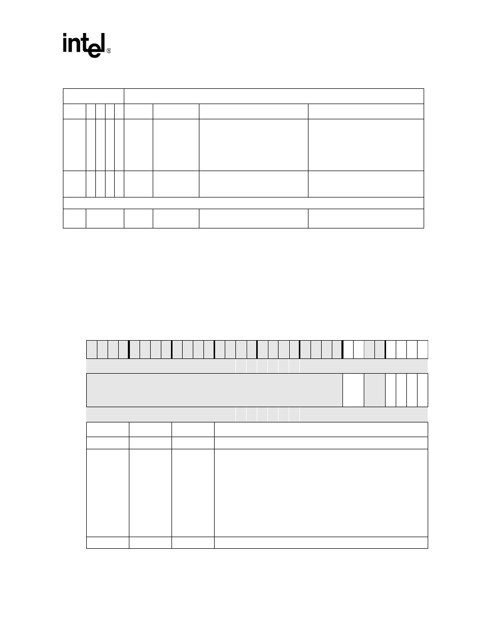
FIFO Control Register (FCR)
The FIFO Control Register (FCR) is a write-only register that is located at the same address as the
IIR, which is a read-only register. The FCR enables/disables the transmitter/receiver FIFOs, clears
the transmitter/receiver FIFOs, and sets the receiver FIFO trigger threshold. The FCR bit
definitions are shown in
.
IID[01] 0
0
1
0
Third
Highest
Transmit FIFO
Data Request
Non-FIFO mode – Transmit Holding
Register Empty
Reading the IIR (if the source of the
interrupt) or writing into the Transmit
Holding Register.
FIFO mode – Transmit FIFO has half
or less than half data.
Reading the IIR (if the source of the
interrupt) or writing to the transmitter
FIFO.
IID[00] 0
0
0
0
Fourth
Highest
Modem Status
Clear to Send, Data Set Ready, Ring
Indicator, Received Line Signal
Detect.
Reading the Modem Status Register.
Non Prioritized Interrupts:
ABL
4
None
Autobaud Lock
indication.
Autobaud circuitry has locked onto
the baud rate.
Reading the IIR
Table 17-9. Interrupt Identification Register Decode (Sheet 2 of 2)
Interrupt ID bits
Interrupt SET/RESET Function
3
2
1
0
Priority
Type
Source
RESET Control
Table 17-10.
FCR Bit Definitions (Sheet 1 of 2)
Physical Address
0x4160_0008
FIFO Control Reg. (FCR)
PXA26x Processor Family Hardware
UART
User
Settings
Bit
31 30 29 28 27 26 25 24 23 22 21 20 19 18 17 16 15 14 13 12 11 10 9
8
7
6
5
4
3
2
1
0
Reserved
ITL
R
eser
ved
TIL
R
ESE
TTF
R
ESE
TRF
T
R
FI
FO
E
Reset
?
?
?
?
?
?
?
?
?
?
?
?
?
?
?
?
?
?
?
?
?
?
?
?
0
0
?
?
0
0
0
0
Bits
Access
Name
Description
31:8
N/A
—
Reserved – Read as unknown and must be written as zero.
7:6
Write
ITL
INTERRUPT TRIGGER LEVEL (threshold):
When the number of bytes in the receiver FIFO equals the interrupt trigger
threshold programmed into this field and the received data available
interrupt is enabled via the IER, an interrupt is generated and appropriate
bits are set in the IIR. The receive DMA request is also generated when the
trigger threshold is reached.
0b00
–
1 byte or more in FIFO causes interrupt (Not valid in DMA mode)
0b01
–
8 bytes or more in FIFO causes interrupt and DMA request
0b10
–
16 bytes or more in FIFO causes interrupt and DMA request
0b11
–
32 bytes or more in FIFO causes interrupt and DMA request
5:4
N/A
—
Reserved – Read as unknown and must be written as zero.