Figure 17-1. example uart data frame, Figure 17-1 – Intel PXA26X User Manual
Page 588
17-4
Intel® PXA26x Processor Family Developer’s Manual
Hardware UART
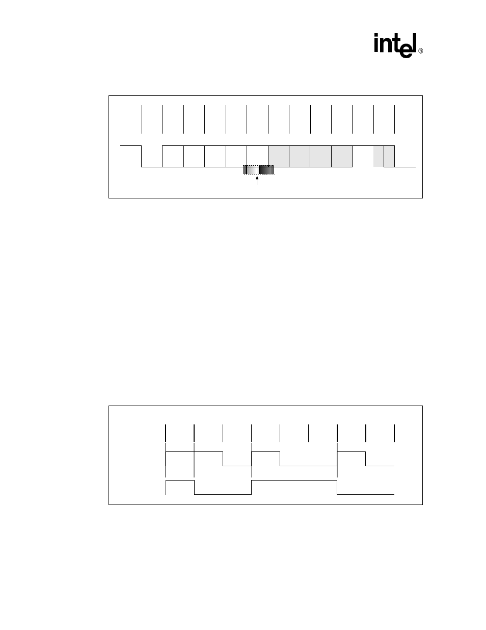
Receive data sample counter frequency is 16 times the value of the bit frequency. The 16X clock is
created by the baud rate generator. Each bit is sampled three times in the middle. Shaded bits in
are optional and can be programmed by software.
Each data frame is between seven and 12 bits long, depending on the size of the data programmed,
whether parity is enabled, and the number of stop bits. A data frame begins by transmitting a start
bit that is represented by a high to low transition. The start bit is followed by from five to eight bits
of data that begin with the least significant bit (LSB). The data bits are followed by an optional
parity bit. The parity bit is set if even parity is enabled and the data byte has an odd number of ones
or if odd parity is enabled and the data byte has an even number of ones. The data frame ends with
one, one and a half or two stop bits, as programmed by software. The stop bits are represented by
one, one and a half, or two successive bit periods of a logic one.
The UART has two FIFOs: one transmit and one receive. The transmit FIFO is 64 bytes deep and
eight bits wide. The receive FIFO is 64 bytes deep and 11 bits wide. Three bits are used for tracking
errors.
The UART can use NRZ coding to represent individual bit values. NRZ coding is enabled when the
Interrupt Enable Register’s (IER) bit 5, IER[5] is set to high. A one is represented by a line
transition and a zero is represented by no line transition.
shows the data byte 0b 0100
1011 in NRZ coding. The byte’s LSB is transmitted first.
Figure 17-1. Example UART Data Frame
Start
Bit
Data
<0>
Data
<1>
Data
<2>
Data
<3>
Data
<4>
Data
<5>
Data
<6>
Data
<7>
Parit
y
Bit
Stop
Bit 1
Stop
Bit 2
TXD or RXD pin
LSB
MSB
Figure 17-2. Example NRZ Bit Encoding (0b0100 1011)
Digital
Data
NRZ
Data
Bit
Value
1
1
0
1
0
0
1
0
LSB
MSB