1 operation, Figure 17-3. ir transmit and receive example – Intel PXA26X User Manual
Page 593
Intel® PXA26x Processor Family Developer’s Manual
17-9
Hardware UART
The SIR interface does not contain the actual IR LED driver or the receiver amplifier. The I/O pins
attached to the SIR only have digital CMOS level signals. The SIR supports two-way
communication, but full duplex communication is not possible because reflections from the
transmit LED enter the receiver. The SIR interface supports frequencies up to 115.2 Kbps.
Because the input clock is 14.7456 MHz, the baud divisor must be eight or more.
17.4.5.1
Operation
The SIR modulation technique works with 5-, 6-, 7-, or 8-bit characters with an optional parity bit.
The data is preceded by a zero value start bit and ends with one or more stop bits. The encoding
scheme is to set a pulse 3/16 of a bit wide in the middle of every zero bit and send no pulses for bits
that are ones. The pulse for each zero bit must occur, even for consecutive bits with no edge
between them.
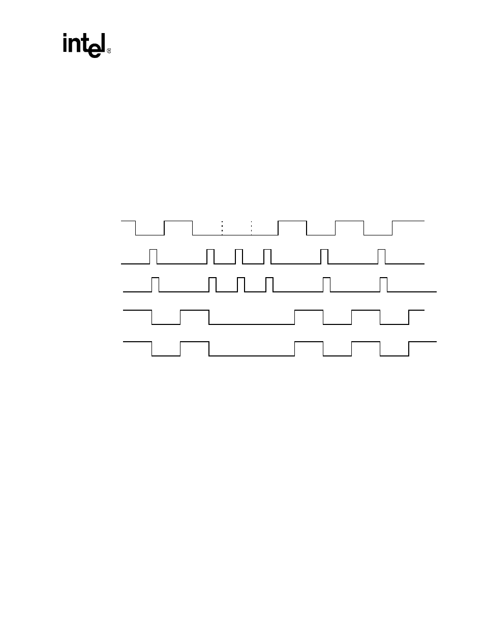
Figure 17-3. IR Transmit and Receive Example
The top line in
shows an asynchronous transmission as it is sent from the UART. The
second line shows the pulses generated by the IR encoder at the TXD pin. A pulse is generated in
the middle of the START bit and any data bit that is a zero. The third line shows the values received
at the RXD input pin. The fourth line shows the receive decoder’s output. The receive decoder
drives the receiver data line low when it detects a pulse. The bottom line shows how the UART’s
receiver interprets the decoder’s action. This last line is the same as the first, but it is shifted half a
bit period.
When XMODE is cleared, each zero bit has a pulse width of 3/16 of a bit time. When XMODE is
set, a pulse of 1.6
µ
s is generated in the middle of each zero bit. The shorter infrared pulse
generated when XMODE is set reduces the LED’s power consumption. At 2400 bps, the LED is
normally on for 78
µ
s for each zero bit that is transmitted. When XMODE is set, the LED is on
only 1.6
µ
Figure 17-4, “XMODE Example.” on page 17-10
).
START
BIT
STOP
BIT
1
0
0
0
1
0
1
0
START
BIT
1
0
0
0
1
0
1
0
TRANSMIT
IR ENCODER OUTPUT
IR DECODER OUTPUT
UART
UART RECEIVE
(TXD PIN VALUE)
SHIFT VALUE
RXD PIN VALUE
SHIFT VALUE
STOP
BIT