Intel PXA26X User Manual
Page 375
Intel® PXA26x Processor Family Developer’s Manual
10-9
Universal Asynchronous Receiver/Transmitter
Note:
When DMA requests are enabled and an interrupt occurs, software must first read the LSR to see if
an error interrupt exists, then check the IIR for the source of the interrupt. When the last error byte
is read from the FIFO, DMA requests are automatically enabled. Software is not required to check
for the error interrupt if DMA requests are disabled because an error interrupt only occurs when
DMA requests are enabled.
Bit 7 of the IER is used to enable DMA requests. The IER also contains the unit enable and NRZ
coding enable control bits. Bits 7 through 4 are used differently from the standard 16550 register
definition.
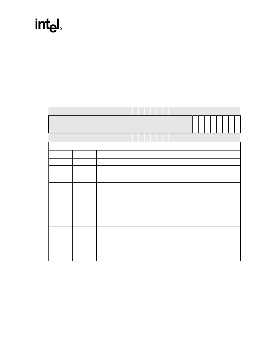
Table 10-7. Interrupt Enable Register
–
IER (Sheet 1 of 2)
Base+0x04 (DLAB=0)
Interrupt Enable Register
UART
Bit
31 30 29 28 27 26 25 24 23 22 21 20 19 18 17 16 15 14 13 12 11 10 9
8
7
6
5
4
3
2
1
0
R
eser
ved
DM
A
E
UU
E
NR
Z
E
RT
O
IE
MI
E
RL
S
E
TIE
RA
VI
E
Reset
0
0
0
0
0
0
0
0
0
0
0
0
0
0
0
0
0
0
0
0
0
0
0
0
0
0
0
0
0
0
0
0
Read/Write
Bits
Name
Description
31:8
—
Reserved
7
DMAE
DMA REQUESTS ENABLE:
0 – DMA requests are disabled
1 – DMA requests are enabled
6
UUE
UART UNIT ENABLE:
0 – The unit is disabled
1 – The unit is enabled
5
NRZE
NRZ CODING ENABLE:
NRZ encoding/decoding is only used in UART mode, not in infrared mode. If the slow
infrared receiver or transmitter is enabled, NRZ coding is disabled.
0 – NRZ coding disabled
1 – NRZ coding enabled
4
RTOIE
CHARACTER TIMEOUT INDICATION INTERRUPT ENABLE:
0 – Character Timeout Indication interrupt disabled
1 – Character Timeout Indication interrupt enabled
3
MIE
MODEM INTERRUPT ENABLE:
0 – Modem Status interrupt disabled
1 – Modem Status interrupt enabled