4 i2c status register, Section 9.9.4, “i2c status register, C status register – Intel PXA26X User Manual
Page 364
9-26
Intel® PXA26x Processor Family Developer’s Manual
Inter-Integrated Circuit Bus Interface Unit
9.9.4
I
2
C Status Register
The ISR signals I
2
C
interrupts to the processor interrupt controller. Software can use the ISR bits to
check the status of the I
2
C unit and bus. ISR bits (bits 9-5) are updated after the ACK/NAK bit is
completed on the I
2
C bus.
The ISR also clears the following interrupts signalled from the I
2
C unit:
•
IDBR receive full
•
IDBR transmit empty
•
Slave address detected
•
Bus error detected
•
STOP condition detect
•
Arbitration lost
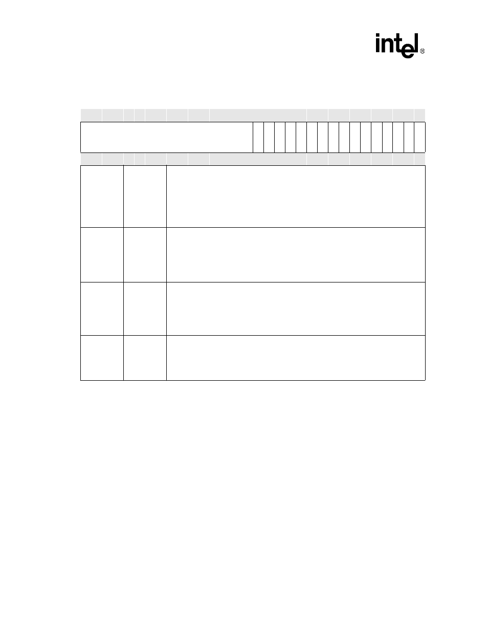
3
TB
TRANSFER BYTE:
Used to send/receive a byte on the I
2
C bus.
0 – Cleared by I
2
C unit when the byte is sent/received.
1 – Send/receive a byte.
The processor can monitor this bit to determine when the byte transfer is completed. In
master or slave mode, after each byte transfer, including ACK/NAK bit, the I
2
C unit holds
the SCL line low (inserting wait states) until the Transfer Byte bit is set.
2
ACKNAK
ACK/NAK CONTROL:
Defines the type of ACK pulse sent by the I
2
C unit when in master-receive mode.
0 – The I
2
C unit sends an ACK pulse after it receives a data byte.
1 – The I
2
C unit sends a negative ACK (NAK) after it receives a data byte.
The I
2
C unit automatically sends an ACK pulse when it responds to its slave address or
when it responds in slave-receive mode, independent of the ACK/NAK control bit setting.
1
STOP
STOP:
Initiates a STOP condition after the next data byte on the I
2
C bus is transferred in master
mode. In master-receive mode, the ACK/NAK control bit must be set along with this bit. See
Section 9.3.3.3, “STOP Condition”
for more details on the STOP state.
0 – Do not send a STOP.
1 – Send a STOP.
0
START
START:
Initiates a START condition to the I
2
C unit when in master mode. See
for more details on the START state.
0 – Do not send a START.
1 – Send a START.
Table 9-11. I
2
C Control Register - ICR (Sheet 3 of 3)
Physical Address
4030_1690
I
2
C Control Register
I
2
C
Bit
31 30 29 28 27 26 25 24 23 22 21 20 19 18 17 16 15 14 13 12 11 10 9
8
7
6
5
4
3
2
1
0
R
ese
rved
FM
UR
SA
DIE
AL
D
IE
SSD
IE
BE
IE
IR
FIE
ITEIE
GC
D
IU
E
SC
L
E
MA
TB
AC
KNA
K
ST
O
P
ST
A
R
T
Reset
0
0
0
0
0
0
0
0
0
0
0
0
0
0
0
0
0
0
0
0
0
0
0
0
0
0
0
0
0
0
0