2 waking up the ac-link, 1 wake up triggered by the codec, Figure 13-8. sdata_in wake up signaling – Intel PXA26X User Manual
Page 475: The minimum sdata_in wake up pulse width is 1 msec, Bitclk not to scale, 2 wake up triggered by the acunit
Intel® PXA26x Processor Family Developer’s Manual
13-13
AC97 Controller Unit
13.5.2
Waking up the AC-link
13.5.2.1
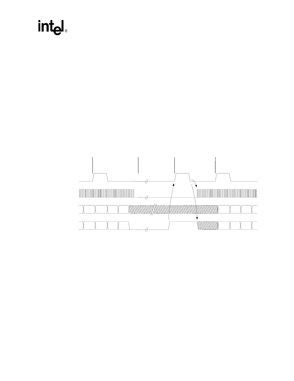
Wake up triggered by the Codec
To wake up the AC-link a codec drives its SDATA_IN to a logic high level. The rising edge
triggers the resume interrupt if that codec’s resume enable bit is set to a 1. The CPU then wakes up
the codec using the cold or warm reset sequence. The ACUNIT uses a warm reset to wake up the
primary codec. The codec detects a warm reset when SYNC is driven high for a minimum of 1
µ
s
and the BITCLK is absent. The codec must wait until it samples SYNC low before it can start
BITCLK. The codec that signaled the wake event must keep its SDATA_IN high until it detects
that a warm reset has been completed. The codec can then transition its SDATA_IN low.
shows the AC-link timing for a wake up triggered by a codec. Because the processor
may need to be awakened, the power management unit detects the AC97 wake-up event
(SDATA_IN high for more than 1
µ
s). When the ACUNIT is ready, it responds to the wake-up
event by asserting a warm or cold reset (see
). A modem codec may require the
capacity to wake up the AC-link to report events such as caller-ID and wake-up-on-ring.
13.5.2.2
Wake Up Triggered by the ACUNIT
AC-link protocol provides for a cold AC97 reset and a warm AC97 reset. The current power-down
state ultimately dictates which AC97 reset is used. Registers must stay in the same state during all
power-down modes unless a cold AC97 reset is performed. In a cold AC97 reset, the AC97
registers are initialized to their default values.
After a power down, the AC-link must wait for a minimum of four audio frame times after the
frame in which the power down occurred before it can be reactivated by reasserting the SYNC
signal. When AC-link powers up, it indicates readiness through the codec ready bit (input slot 0,
bit 15).
Figure 13-8. SDATA_IN Wake Up Signaling
NOTES:
1. After SDATA_IN goes high, SYNC must be held for a minimum of 1
µ
Sec.
2. The minimum SDATA_IN wake up pulse width is 1
µ
Sec.
3. BITCLK not to scale
SDATA_OUT
TAG
SYNC
BITCLK
Write to
0x26
Data
PR4
slot 12
prev. frame
TAG
slot 12
prev. frame
SDATA_IN
TAG
Slot 1
Slot 2
Power Down
Wake Event
Codec Sleep State
New Audio
TAG
Slot 1
Slot 2
Note 1
Note 2