Intel PXA26X User Manual
Page 44
2-14
Intel® PXA26x Processor Family Developer’s Manual
System Architecture
FFRTS/
GPIO[41]
ICOCZ
FULL FUNCTION UART REQUEST-TO-SEND (output):
Pulled High
Note [1]
Note [3]
Bluetooth UART Pins
BTRXD/
GPIO[42]
ICOCZ
BLUETOOTH UART RECEIVE (input):
Pulled High
Note [1]
Note [3]
BTTXD/
GPIO[43]
ICOCZ
BLUETOOTH UART TRANSMIT (output):
Pulled High
Note [1]
Note [3]
BTCTS/
GPIO[44]
ICOCZ
BLUETOOTH UART CLEAR-TO-SEND (input):
Pulled High
Note [1]
Note [3]
BTRTS/
GPIO[45]
ICOCZ
BLUETOOTH UART DATA-TERMINAL-READY (output):
Pulled High
Note [1]
Note [3]
Standard UART and ICP Pins
IRRXD/
GPIO[46]
ICOCZ
IRDA RECEIVE SIGNAL (input):
Receive pin for the FIR function.
STANDARD UART RECEIVE (input)
Pulled High
Note [1]
Note [3]
IRTXD/
GPIO[47]
ICOCZ
IRDA TRANSMIT SIGNAL (output):
Transmit pin for the Standard UART, SIR and FIR
functions.
STANDARD UART TRANSMIT (output)
Pulled High
Note [1]
Note [3]
MMC Controller Pins
MMCMD
ICOCZ
MULTIMEDIA CARD COMMAND (bidirectional)
Hi-Z
Hi-Z
MMDAT
ICOCZ
MULTIMEDIA CARD DATA (bidirectional)
Hi-Z
Hi-Z
nPCE[2]/
GPIO[53]
ICOCZ
PCMCIA CARD ENABLE 2 (outputs):
Selects a PCMCIA card. Bit one enables the high byte
lane and bit zero enables the low byte lane.
MMC clock. (output) Clock signal for the MMC Controller.
Pulled High
Note [1]
Note [5]
L_DD[9]/
GPIO[67]
ICOCZ
LCD DISPLAY DATA (output):
Transfers pixel information from the LCD Controller to the
external LCD panel.
MMC CHIP SELECT 0 (output):
Chip select 0 for the MMC Controller.
Pulled High
Note [1]
Note [3]
L_DD[10]/
GPIO[68]
ICOCZ
LCD DISPLAY DATA (output):
Transfers pixel information from the LCD Controller to the
external LCD panel.
MMC CHIP SELECT 1 (output):
Chip select 1 for the MMC Controller.
Pulled High
Note [1]
Note [3]
L_DD[11]/
GPIO[69]
ICOCZ
LCD DISPLAY DATA (output):
Transfers pixel information from the LCD Controller to the
external LCD panel.
MMC CLOCK (output):
Clock for the MMC Controller.
Pulled High
Note [1]
Note [3]
FFRXD/
GPIO[34]
ICOCZ
FULL FUNCTION UART RECEIVE (input)
MMC CHIP SELECT 0 (output):
Chip select 0 for the MMC Controller.
Pulled High
Note [1]
Note [3]
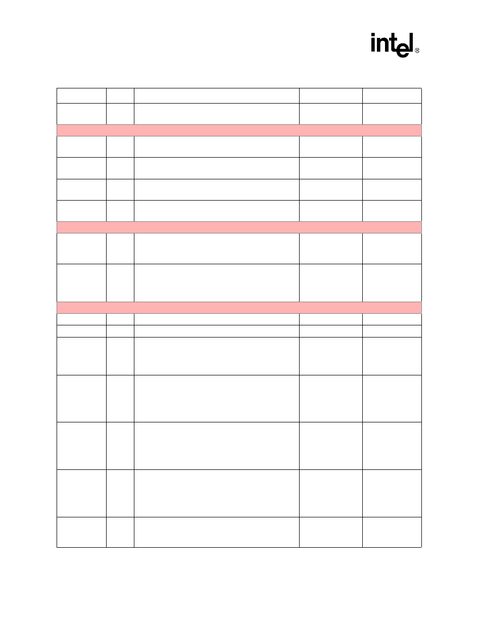
Table 2-6. Pin & Signal Descriptions for the PXA26x Processor Family (Sheet 6 of 12)
Pin Name
Type
Signal Descriptions
Reset State
Sleep State