Table 4-15. grer0 bit definitions, Table 4-16. grer1 bit definitions, Table 4-17. grer2 register bitmap – Intel PXA26X User Manual
Page 122: Table 4-15, Table 4-17
4-14
Intel® PXA26x Processor Family Developer’s Manual
System Integration Unit
Note:
For reserved bits in GRER2 and GFER2, writes must be zeros and reads must be ignored.
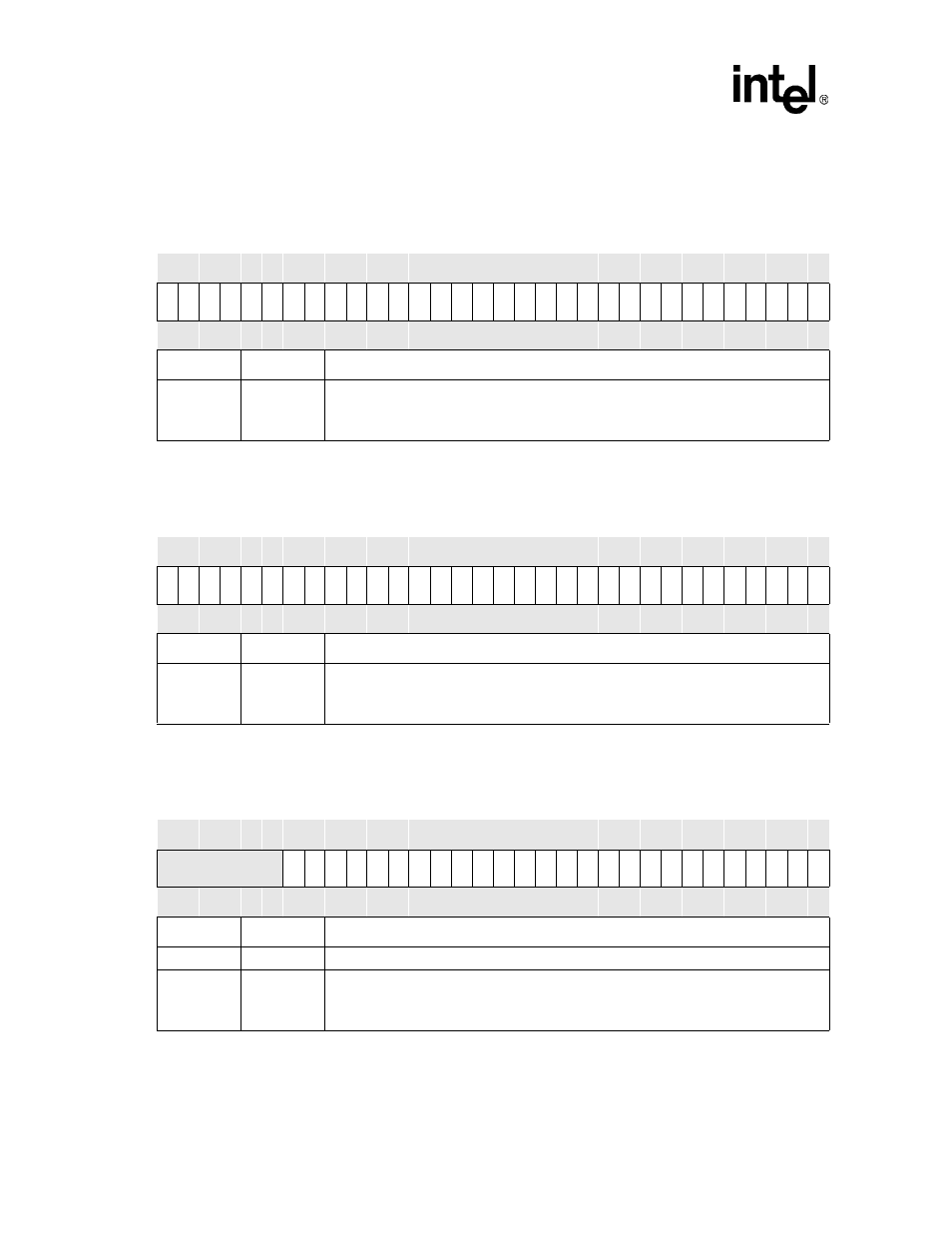
Table 4-15. GRER0 Bit Definitions
Physical Address
0x40E0_0030
GRER0
System Integration Unit
Bit
31 30 29 28 27 26 25 24 23 22 21 20 19 18 17 16 15 14 13 12 11 10 9
8
7
6
5
4
3
2
1
0
RE
3
1
RE
3
0
RE
2
9
RE
2
8
RE
2
7
RE
2
6
RE
2
5
RE
2
4
RE
2
3
RE
2
2
RE
2
1
RE
2
0
RE
1
9
RE
1
8
RE
1
7
RE
1
6
RE
1
5
RE
1
4
RE
1
3
RE
1
2
RE
1
1
RE
1
0
RE
9
RE
8
RE
7
RE
6
RE
5
RE
4
RE
3
RE
2
RE
1
RE
0
Reset
0
0
0
0
0
0
0
0
0
0
0
0
0
0
0
0
0
0
0
0
0
0
0
0
0
0
0
0
0
0
0
0
Bits
Name
Description
<31:0>
RE[x]
GPIO Pin ‘x’ Rising Edge Detect Enable (where x = 0 through 31).
0 – Disable rising-edge detect enable.
1 – Set corresponding GEDR status bit when a rising edge is detected on the GPIO pin
Table 4-16. GRER1 Bit Definitions
Physical Address
0x40E0_0034
GRER1
System Integration Unit
Bit
31 30 29 28 27 26 25 24 23 22 21 20 19 18 17 16 15 14 13 12 11 10 9
8
7
6
5
4
3
2
1
0
RE
6
3
RE
6
2
RE
6
1
RE
6
0
RE
5
9
RE
5
8
RE
5
7
RE
5
6
RE
5
5
RE
5
4
RE
5
3
RE
5
2
RE
5
1
RE
5
0
RE
4
9
RE
4
8
RE
4
7
RE
4
6
RE
4
5
RE
4
4
RE
4
3
RE
4
2
RE
4
1
RE
4
0
RE
3
9
RE
3
8
RE
3
7
RE
3
6
RE
3
5
RE
3
4
RE
3
3
RE
3
2
Reset
0
0
0
0
0
0
0
0
0
0
0
0
0
0
0
0
0
0
0
0
0
0
0
0
0
0
0
0
0
0
0
0
Bits
Name
Description
<31:0>
RE[x]
GPIO Pin ‘x’ Rising Edge Detect Enable (where x = 32 through 63).
0 – Disable rising-edge detect enable.
1 – Set corresponding GEDR status bit when a rising edge is detected on the GPIO pin
Table 4-17. GRER2 Register Bitmap
Physical Address
0x40E0_0038
GPIO Rising Edge Detect Enable
Register2 (GRER2)
System Integration Unit
Bit
31 30 29 28 27 26 25 24 23 22 21 20 19 18 17 16 15 14 13 12 11 10 9
8
7
6
5
4
3
2
1
0
Reserved
RE
8
9
RE
8
8
RE
8
7
RE
8
6
RE
8
5
RE
8
4
RE
8
3
RE
8
2
RE
8
1
RE
8
0
RE
7
9
RE
7
8
RE
7
7
RE
7
6
RE
7
5
RE
7
4
RE
7
3
RE
7
2
RE
7
1
RE
7
0
RE
6
9
RE
6
8
RE
6
7
RE
6
6
RE
6
5
RE
6
4
Reset
0
0
0
0
0
0
0
0
0
0
0
0
0
0
0
0
0
0
0
0
0
0
0
0
0
0
0
0
0
0
0
0
Bits
Name
Description
<31:26>
—
Reserved
<25:0>
RE[x]
GPIO Pin ‘x’ Rising Edge Detect Enable (where x = 64 through 89).
0 – Disable rising-edge detect enable.
1 – Set corresponding GEDR status bit when a rising edge is detected on the GPIO pin