Figure 6-25 – Intel PXA26X User Manual
Page 255
Intel® PXA26x Processor Family Developer’s Manual
6-65
Memory Controller
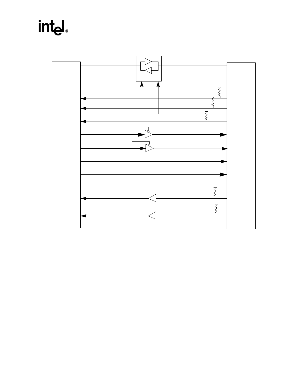
Figure 6-25. Expansion Card External Logic for a One-Socket Configuration
shows the glue logic need for a two-socket system. RDY/nBSY signals are routed
through a buffer to two separate GPIO pins. In the data bus transceiver control logic, nPCE1
controls the enable for the low byte lane and nPCE2 controls the enable for the high byte lane.
MD<15:0>
D<15:0>
nOE
DIR
nCD<1>
nCD<2>
RDY/nBSY
A[25:0]
nREG
nCE<2:1>
nOE
nWE
nIOR
nIOW
nWAIT
nIOIS16
GPIO
GPIO
MA[25:0]
nPREG
nPOE
nPWE
nPIOR
nPIOW
nPWAIT
nIOIS16
nPCE<2:1>
GPIO
PSKTSEL
RD/nWR
GPIO
PXA26x Processor Family
Socket 0
nPCD0
nPCD1
PRDY_BSY0
PADDR_EN0
5V to 3.3V or 2.5V
5V to 3.3V or 2.5V