5 gpio edge detect status register (gedr), Table 4-21. gedr0 bit definitions – Intel PXA26X User Manual
Page 124
4-16
Intel® PXA26x Processor Family Developer’s Manual
System Integration Unit
4.1.3.5
GPIO Edge Detect Status Register (GEDR)
The GPIO Edge Detect Status registers (GEDR0, GEDR1, GEDR2) contain a total of 90 status bits
that correspond to the 90 GPIO pins. When an edge detect occurs on a pin that matches the type of
edge programmed in the GRER or GFER registers, the corresponding status bit is set in GEDR.
Once a GEDR bit is set by an edge event the bit remains set until the user clears it by writing a one
to the status bit. Writing a zero to a GEDR status bit has no effect.
Each edge detect that sets the corresponding GEDR status bit for GPIO[89:0] can trigger an
interrupt request. GPIO[89:2] together form a group that can cause one interrupt request to be
triggered when any one of GEDR[89:2] are set. GPIO[0] and GPIO[1] cause independent first-
level interrupts. Refer to
Section 4.2, “Interrupt Controller” on page 4-22
, for a description of the
programming of GPIO interrupts.
through
show the bitmaps of the GPIO Edge Detect Status registers.
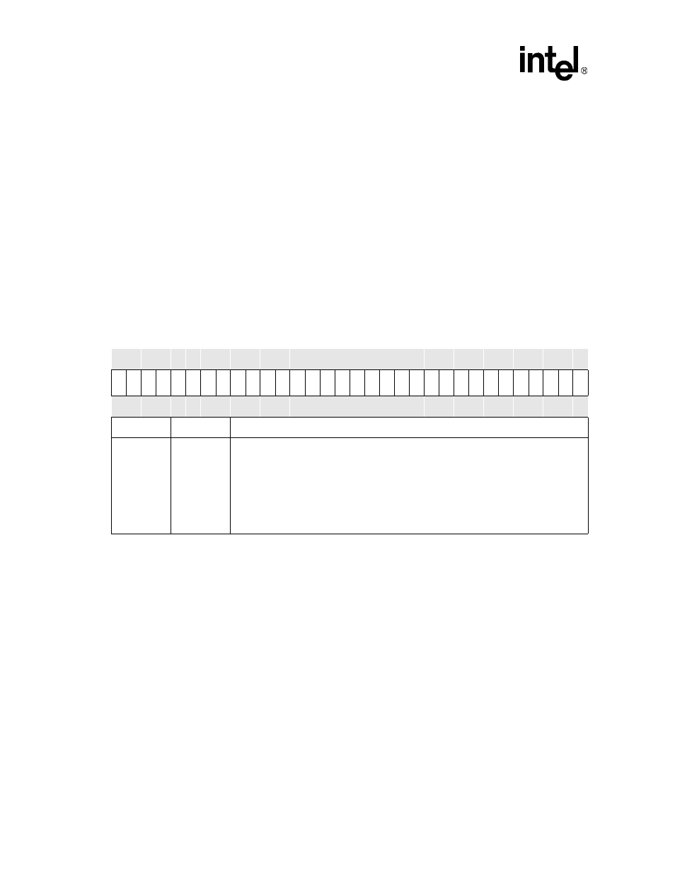
Table 4-21. GEDR0 Bit Definitions
Physical Address
0x40E0_0048
GEDR0
System Integration Unit
Bit
31 30 29 28 27 26 25 24 23 22 21 20 19 18 17 16 15 14 13 12 11 10 9
8
7
6
5
4
3
2
1
0
ED
3
1
ED
3
0
ED
2
9
ED
2
8
ED
2
7
ED
2
6
ED
2
5
ED
2
4
ED
2
3
ED
2
2
ED
2
1
ED
2
0
ED
1
9
ED
1
8
ED
1
7
ED
1
6
ED
1
5
ED
1
4
ED
1
3
ED
1
2
ED
1
1
ED
1
0
ED
9
ED
8
ED
7
ED
6
ED
5
ED
4
ED
3
ED
2
ED
1
ED
0
Reset
0
0
0
0
0
0
0
0
0
0
0
0
0
0
0
0
0
0
0
0
0
0
0
0
0
0
0
0
0
0
0
0
Bits
Name
Description
<31:0>
ED[x]
GPIO PIN ‘X’ EDGE DETECT STATUS (where x = 0 through 31):
READ
0 – No edge detect has occurred on pin as specified in GRER or GFER.
1 – Edge detect has occurred on pin as specified in GRER or GFER.
WRITE
0 – No effect.
1 – Clear edge detect status field.