Table 4-48. ossr bit definitions, 3 operating system timer register locations, Table 4-49. os timer register locations – Intel PXA26X User Manual
Page 150
4-42
Intel® PXA26x Processor Family Developer’s Manual
System Integration Unit
4.4.3
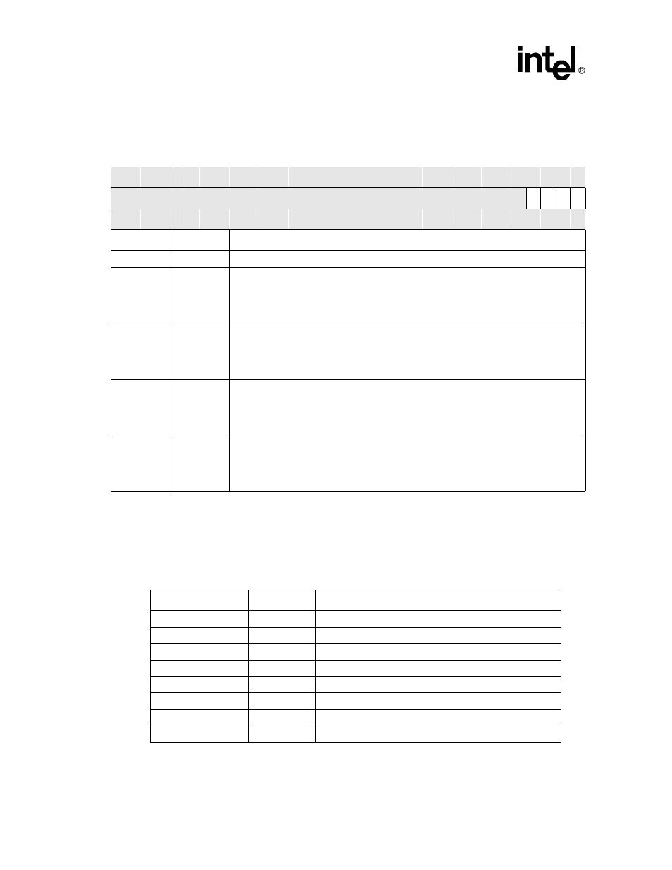
Operating System Timer Register Locations
shows the registers associated with the OS timer and the physical addresses used to
access them.
Table 4-48. OSSR Bit Definitions
Physical Address
0x40A0_0014
OS Timer Status Register (OSSR)
System Integration Unit
Bit
31 30 29 28 27 26 25 24 23 22 21 20 19 18 17 16 15 14 13 12 11 10 9
8
7
6
5
4
3
2
1
0
Reserved
M3
M2
M1
M0
Reset
?
?
?
?
?
?
?
?
?
?
?
?
?
?
?
?
?
?
?
?
?
?
?
?
?
?
?
?
0
0
0
0
Bits
Name
Description
<31:4>
—
Reserved
<3>
M3
MATCH STATUS CHANNEL 3:
If OIER[3] is set then:
0 – OSMR[3] has NOT matched the OS timer counter since last being cleared.
1 – OSMR[3] has matched the OS timer counter.
<2>
M2
MATCH STATUS CHANNEL 2:
If OIER[2] is set then:
0 – OSMR[2] has NOT matched the OS timer counter since last being cleared.
1 – OSMR[2] has matched the OS timer counter.
<1>
M1
MATCH STATUS CHANNEL 1:
If OIER[1] is set then:
0 – OSMR[1] has NOT matched the OS timer counter since last being cleared.
1 – OSMR[1] has matched the OS timer counter.
<0>
M0
MATCH STATUS CHANNEL 0:
If OIER[0] is set then:
0 – OSMR[0] has NOT matched the OS timer counter since last being cleared.
1 – OSMR[0] has matched the OS timer counter.
Table 4-49. OS Timer Register Locations
Address
Name
Description
0x40A0_0000
OSMR0
OS timer match register 0
0x40A0_0004
OSMR1
OS timer match register 1
0x40A0_0008
OSMR2
OS timer match register 2
0x40A0_000C
OSMR3
OS timer match register 3
0x40A0_0010
OSCR
OS timer counter register
0x40A0_0014
OSSR
OS timer status register
0x40A0_0018
OWER
OS timer watchdog enable register
0x40A0_001C
OIER
OS timer interrupt enable register