Figure 11-2. 4ppm modulation example, 2 frame format – Intel PXA26X User Manual
Page 397
Intel® PXA26x Processor Family Developer’s Manual
11-3
Fast Infrared Communication Port
11.2.2
Frame Format
The frame format used with 4-Mbps transmission is shown in
.
Figure 11-3. Frame Format for IrDA Transmission (4.0 Mbps)
The preamble, start, and stop flags are a mixture of chips that contain 0, 1, or 2 pulses in their
timeslots. Chips with 0 and 2 pulses are used to construct flags because the chips represent invalid
data bit pairings. The preamble contains 16 repeated transmissions of the chips: 1000 0000 1010
1000. The start flag contains one transmission of eight chips: 0000 1100 0000 1100 0110 0000
0110 0000. The stop flag contains one transmission of eight chips: 0000 1100 0000 1100 0000
0110 0000 0110. The address, control, data, and CRC-32 use the standard 4PPM chip encoding to
represent two bits per chip.
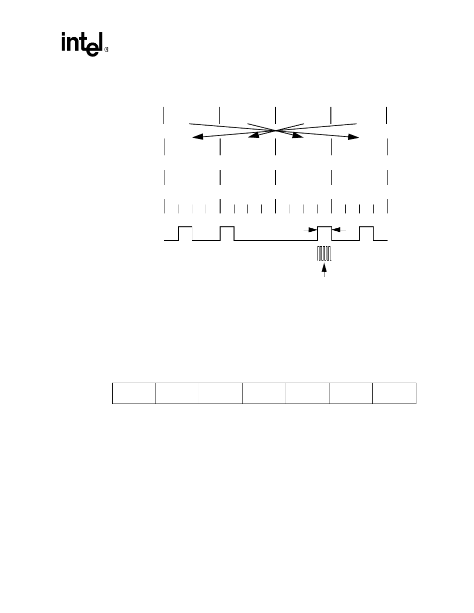
Figure 11-2. 4PPM Modulation Example
4PPM
Data
Reordered
Nibbles
0
1
0
0
1
1
1
0
125 ns
Timeslots
1
2
3
4
1
2
3
4
1
2
3
4
1
2
3
4
Chips
1
2
3
4
Receive data sample counter frequency = 6/pulse width. Each timeslot is sampled on the third cloc
Original
Byte Order
1
0
1
1
0
0
0
1
Nibble 3
Nibble 2
Nibble 1
Nibble 0
Nibble 0
Nibble 1
Nibble 2
Nibble 3
48 MHz
64 chips
8 chips
4 chips
(8 bits)
4 chips
(8 bits)
8180 chips
max
(2045 bytes)
16 chips
(32 bits)
8 chips
Preamble
Start Flag
Address
(optional)
Control
(optional)
Data
CRC-32
Stop Flag
Preamble -
| 1000 | 0000 | 1010 | 1000 |... repeated at least 16 times
Start flag -
| 0000 | 1100 | 0000 | 1100 | 0110 | 0000 | 0110 | 0000 |
Stop Flag -
| 0000 |1100 | 0000 | 1100 | 0000 | 0110 | 0000 | 0110 |